
RL02 drive measurements

I have version 3 of the RL02 controller, which looks as follows:
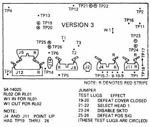
The version 3 controller board layout, with the test points and the jumper table: 19-20 defeats cover closed, 23-24 disables SKTO and 25-26 defeats POS SIG.

First test is the sector pulse timing check. For that the oscilloscope is on TP14. The signal looks as follows:
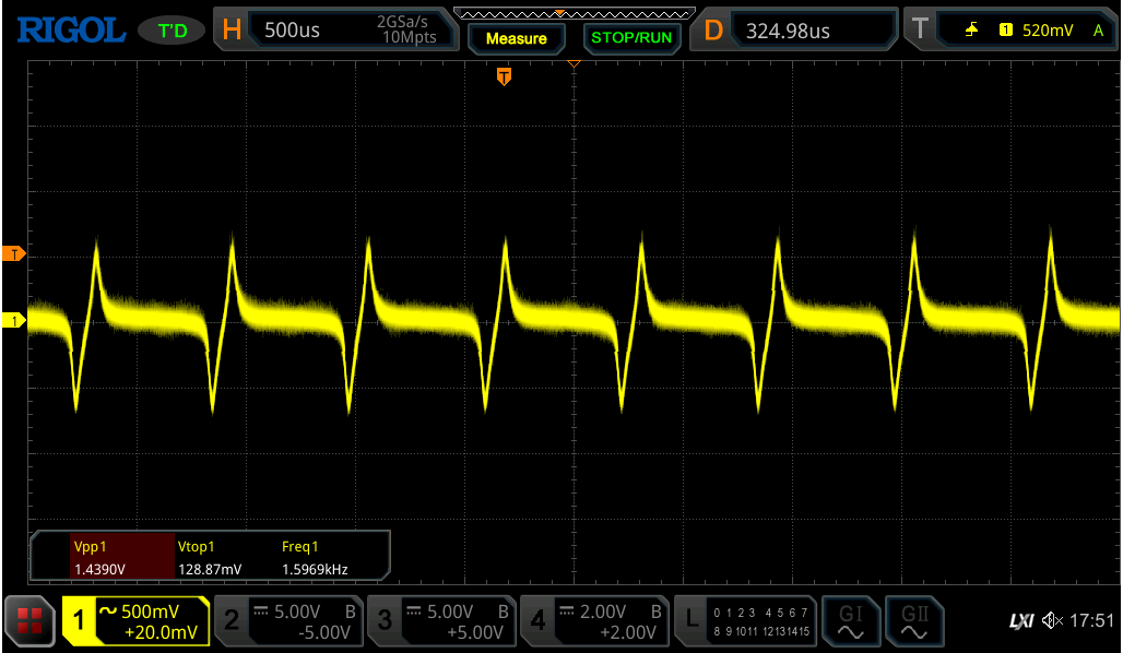
The sector pulse on TP14 at 1.5969kHz. The downward excursion is about -0.7V, inside spec.

According to the docs this should be:
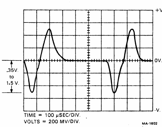
What the manual asks for: a negative excursion of 0.35V to 1.5V at 100us per division.

The downward voltage is about -0.7V which is within spec. The pulse width is 625uS which is ok (624uS is the medior).

Second is sector pulse width on TP11:
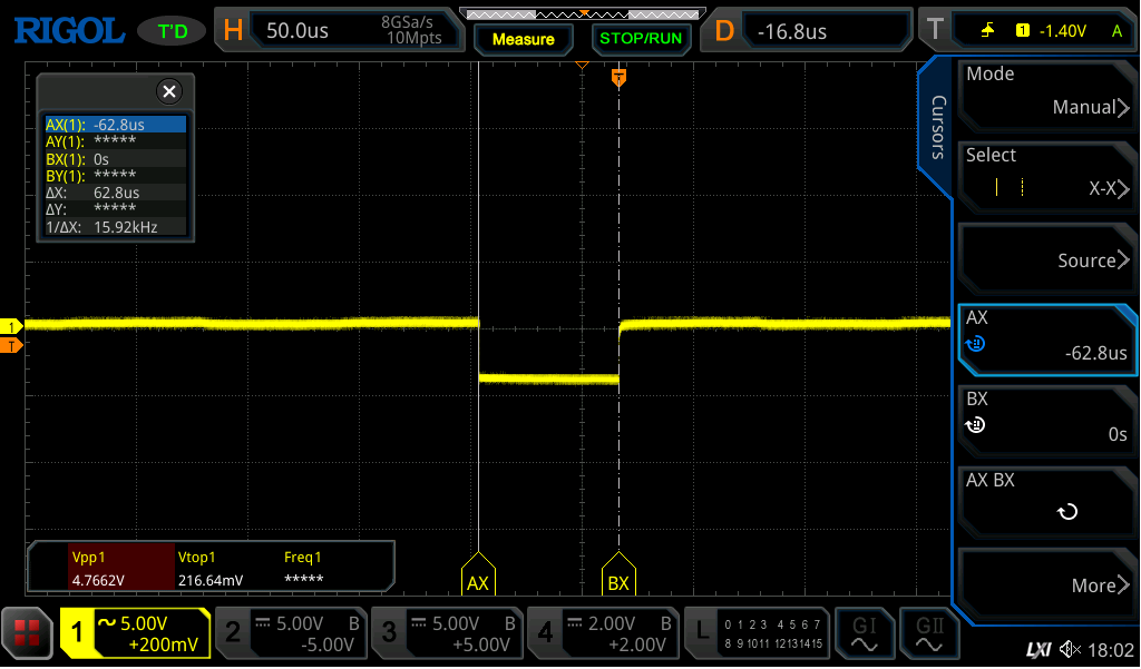
The pulse width on TP11 measured with cursors: 62.8us against the 62.5us specified.

This should be 62.5uS; 62.8 seems close enough.

Positioner radial alignment:

We need to disable:

  • SKTO (strap on tp23-tp24)
  • Cover closed (strap 19-20)
  • POS SIG (strap 25-26)

Place probe A on TP11 (sector pulse), place probe B on TP2 in the WRITE module.

The manual says this:
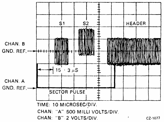
The alignment picture from the manual: the servo bursts S1 and S2 followed by the header, with the burst arriving 15 +/- 3us after the sector pulse.

This manual image is confusing. It shows chA at 500mv/Div, and the pulse at 2divs = 1V. But we measured that pulse in the previous test and it is at 5V. I think the values have been swapped and channel A is on 2v/div and B is at 500mv. So the correct picture is this:
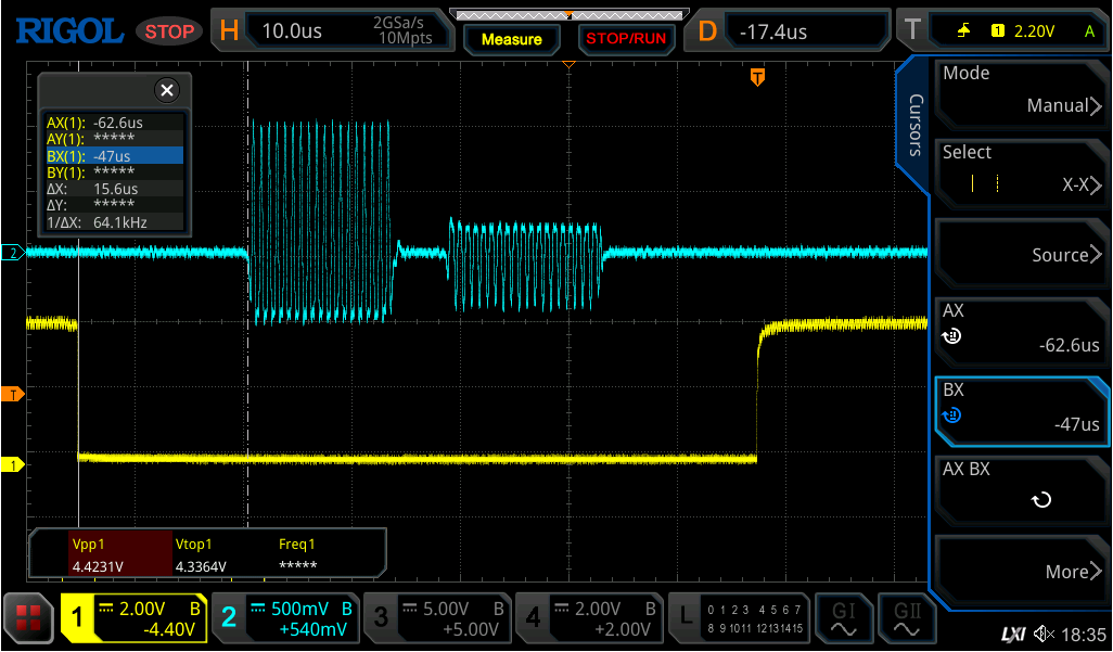
The same measurement on the drive, with channel A at 2V and channel B at 500mV per division. The servo burst arrives at 15.6us, well inside the window.

This looks OK; the servo burst arrives at 15.6 uS

Jitter fix

While doing the Head Alignment test I found that the signal had a very large amount of "jitter":

Drive Jitter

Doing the alignment reduced that to within spec (15 uS +/- 3 uS).

Last modified: 2026/09/06