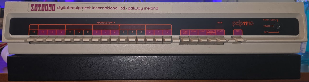
The PDP 11/10
I got this beauty from Geert again, thanks a lot!
This is one of the earliest PDP 11's. The type was introduced in 1972. The 11/10 is the exact same machine as the 11/05; only the printed label on the console changes, nothing else. The 11/10 was meant for end users while the 11/05 was for the OEM market. All documentation refers to the 11/05. Mine is one of the early models in a 5 1/4" box:
The machine came empty, but with a full set of cards (see pdp card inventory).
What goes inside
Boards and board layout
According to Gunkies the board layout changes depending on the backplane model number. This number cannot be seen on my machine, but it came with Unibus terminators in slot#5 and #7, and 4 G727A BR passthrough cards in slots 6 to 9, so I assume my backplane is #54-09818 which should have the following configuration:
| Connector |
| Slot | A B | C D E F |
|---|---|---|
| 1 | M7260 KD11-A CPU board #0 | |
| 2 | M7261 KD11-A CPU board #1 | |
| 3 | G110/G109C Memory Control | |
| 4 | G231 Memory Driver | |
| 5 | UNIBUS Terminator | H213/H214 Core stack |
| 6 | Unused | SPC |
| 7 | UNIBUS Out | SPC |
| 8 | KM11-1 KM11-2 | SPC |
| 9 | DF11 | SPC |
Slot #1 is at the bottom. Checked against the 11/05 engineering drawings.
About G109C / G110
The engineering drawings talk about the G110 board, as does most of the public documentation. I actually only have G109C boards. The difference is that G109 boards have two extra "parity" bit channels and the G110 does not. These channels are not useful on an 11/05 because there is nothing using them; the H214 core stack does not have them either. The G110 is the same PCB (so also marked as G109) but with the extra channels unpopulated (details from Gunkies). .
Multiple machine revisions..
There have been multiple revisions of this machine's internals. I found the following engineering drawing sets:
- BitSavers revision AH from Jul 76. This seems to match with M7261F boards.
- pdp-11-05-engineering-drawings-oct-1973, uploaded by 1944GW. This matches the M7261E board.
The user manual I have (DEC-11-H05AA-A-D_1105um) is for the 1973 revision (A-D).
Getting the machine to work (in progress)
- The power supply
- First power-up
- Getting the console to work
- Trying memory to respond
- The SCL system console
- The M9312 bootstrap terminator
The status of the different boards
I have about 4 copies of every board. Which one of them works and which ones do not:
Current loop converter and hidden 5V RS-232
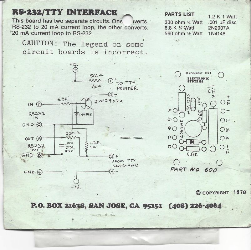
The 11/05 uses a current loop for the console. The following old schematic is a conversion from current loop to RS232 and vice versa: