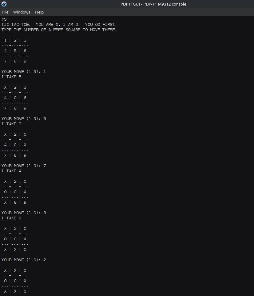
The M9312 bootstrap terminator
This board combines a terminator with a set of bootstrap ROMs:
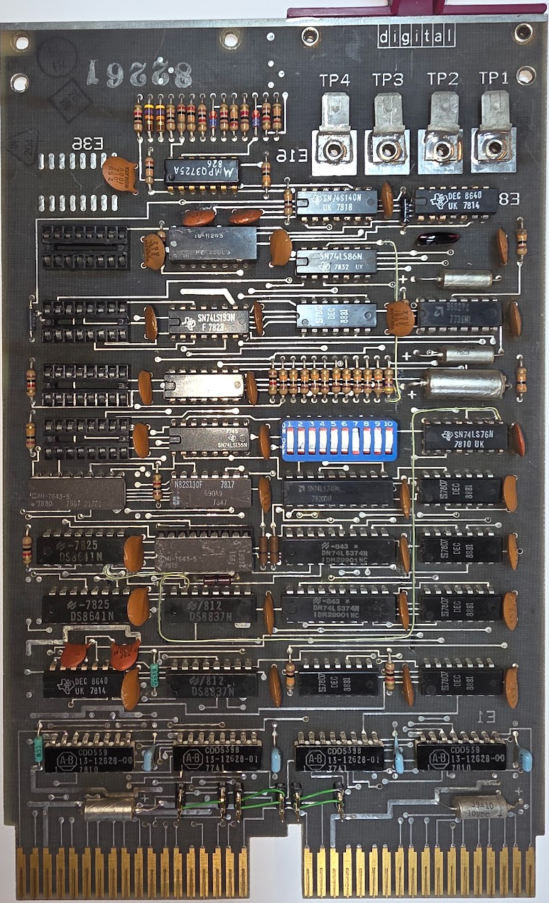
It has the following PROMs on it:
- 690a9 (N82S130F): ?
- 248f1 (MI-7643-5): M9312 pdp-11/04/05/34/35/40/45/50/55 Console Emulator and Diagnostic
- 217f1 (MI-7643-5) ?
(The numbers for these PROMs can be found here and here).
After installing the M9312 in place of the topmost terminator the test is to see whether it starts, as follows:
- Enter 165020 on the switches
- Move halt upwards (not halted)
- Press start
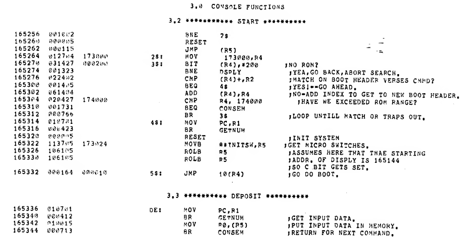
If all goes well this should show the @ prompt on the SCL console. Of course this did not go well; the CPU stopped at 1653348. This contains the following according to the listing:
The second attempt started at 1651448, which should skip the diagnostics. This ended at 1654068:
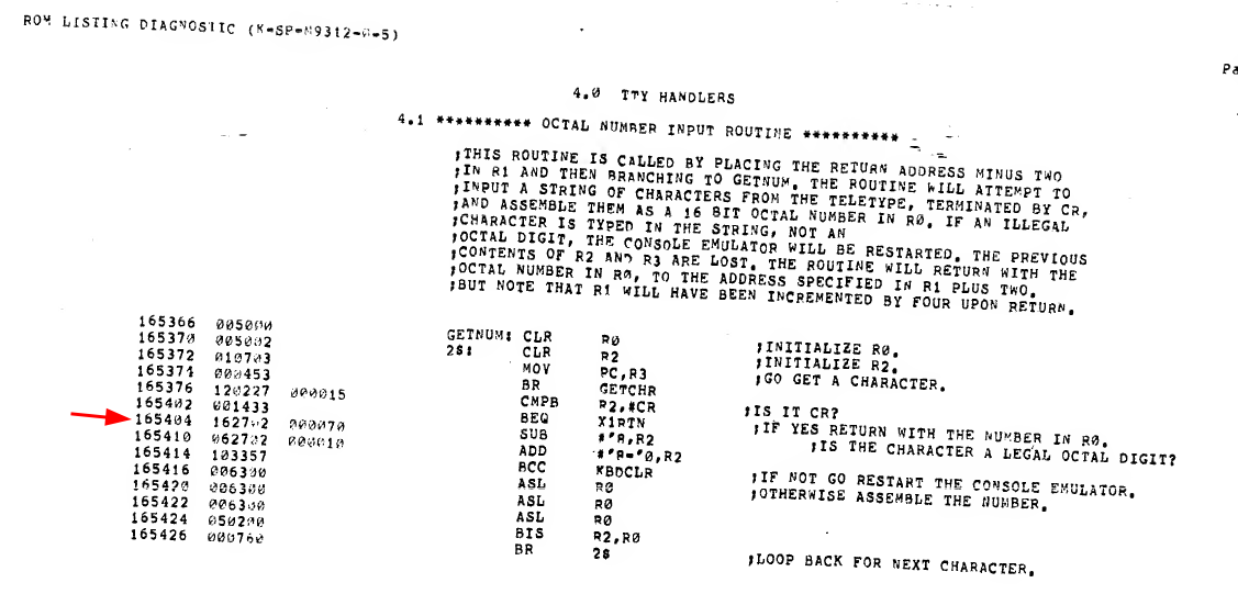
Neither looks good. I examined the code at 165144, and that does not look at all like the listing. Next check is the PROM contents. The MI-7643-5 is an 1kx4 PROM, an equivalent is 82S137, and this can be read by the TL866. There is one nibble different in my PROM compared to the listing from here:
:100000000000060F0000060F00000C090F0F030E82 Published
:100000000000000F0000060F00000C090F0F030E88 Mine
a single 6 is missing. That does not explain the totally different code from the examine.
Quick test: replace the M930 terminator, and checks that nothing else answers at 165144; that caused a bus error so no.
I read the first values from the PROM, starting at address 165144:
020427
174000
001731
000763
010701
000423
and asked Claude to compare it with the 23-248f1 listing. It found out that this is real ROM contents but from a different address:
| Address you examined | You read | Listing at that address | Listing at +140 |
|---|---|---|---|
| 165144 | 020427 | 010701 | 165304: 020427 |
| 165146 | 174000 | 000554 | 165306: 174000 |
| 165150 | 001731 | 010701 | 165310: 001731 |
| 165152 | 000763 | 000526 | 165312: 000766 |
| 165154 | 010701 | 010400 | 165314: 010701 |
| 165156 | 000423 | 000524 | 165316: 000423 |
This points to an address error:
165144 has bits 5 and 2 set in its ROM offset (144 = 001 100 100). 165304 has bits 7 and 2 set (304 = 011 000 100). So Unibus address bit 5 is arriving as 0 and bit 7 as 1. Bits 1–4 are fine, since the whole run of consecutive addresses stays lined up. Two faults fit this:
- A05 and A07 are swapped, for example crossed traces, a solder bridge, or a wrong jumper wire from an earlier repair.
- A05 is stuck low and A07 is stuck high.
Two examines will tell them apart:
165000: should read 165000. If it reads 112702, A07 is stuck high. 165200: should read 112702. If it reads 005303, the lines are swapped.
The examine showed 165000 AND 165200 both had 112702, so A7 is stuck high. Examining 165040 also shows 112702; it should have been 042440. This means A5 is stuck low.
The PROM is E20 on the board.
Short overview of how the module works
All PROMs are 4 bit proms. Their outputs are connected to E12, a 74LS374 latch. The outputs of the first 4 bits of the latch are connected to the inputs of the second 4 bits of that same latch. The outputs of those bits are then connected to the inputs of the second 74LS374 latch (E11), and those outputs again go to the last 4 inputs.
This forms a shift register where every clock shifts the existing data 4 bits upward while clocking in the data from the PROMs. The first 2 address bits of each PROM are fed by a byte counter which increments the address while the bus address remains the same; this shifts all nibbles into the latches, forming the actual data word to be read by the CPU.
A07 H and A05 H come directly from the Unibus receivers:
- A07 H from E18; P5 is the bus, P6 is the output.
- A05 H from E18; P13 is the bus, P12 is the output.
The LA shows that there is indeed a problem, when examining 165200:
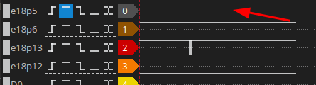
This one needs a replacement. I actually have them in stock for a change  . Desoldering was a crime but in the end it worked and I placed a low profile socket with a new DS8837, and lo and behold - 165000 read 165000, and 165200 read 112702.
Retrying the console..
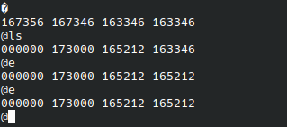
With the replacement the PROMs look OK, and indeed: starting it at 165144 shows:
Auto-starting the console PROM
Auto-booting the console PROM from the M9312 requires the following settings in S1:
ON ON OFF OFF ON ON OFF OFF ON OFF
This should define the console PROM without diagnostics. Sadly enough nothing happens when I set that, so there's another issue.
Auto boot works by recognizing the CPU's reset sequence. After reset the CPU fetches PC and PSW from address 24oct and 26oct normally. But when auto boot is enabled the M9312 forces additional address lines HIGH during RESET causing the addresses to be read to be 773024oct and 773026oct. I checked reading data at 173024, which according to the docs should return the PC that the machine should use, but that just causes a bus error.. What should live at that address?
These addresses actually fall within the address range of boot PROM 1:
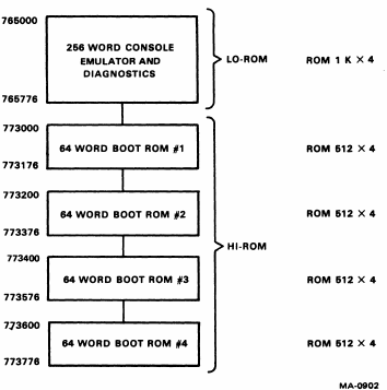
and when you look at the boot prom format description it has this suspicious information:
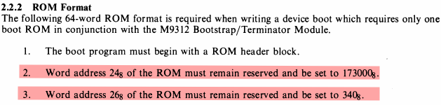
This leads me to believe that this boot process will ONLY work when at least one PROM is present.. I have a TU80 boot PROM (23-764A9) from the 11/44 M7098 Unibus adapter that I cannot use. Dumping that PROM shows that it does obey that format:
173000: 046523 000176 000660 012301
173010: 000000 012701 172123 010305
173020: 103462 000411 173000 000340 <-- last two words
173030: 142010 000000 000000 001000
173040: 140004 001012 000000 010402
173050: 010303 012705 001022 014644
173060: 105705 001774 006702 006702
173070: 060700 010102 005343 105711
173100: 100376 005436 000000 012313
173110: 001010 111502 100376 010113
173120: 105711 100376 032711 000012
173130: 001346 012715 140400 105502
173140: 100366 010113 105711 100376
173150: 005711 100401 005406 012715
173160: 161400 105502 100366 000727
173170: 000536 165165 000000 140327
Placing the prom in E35 (the open slot at the top of the adapter, closest to the handle) indeed makes the machine boot into the console program.
Making the machine work with pdp11javagui
I rewrote PDP11Gui in Java because I refuse to use Windows. Next round it to make it connect to the 11/05 and make it do something.. It works nicely:
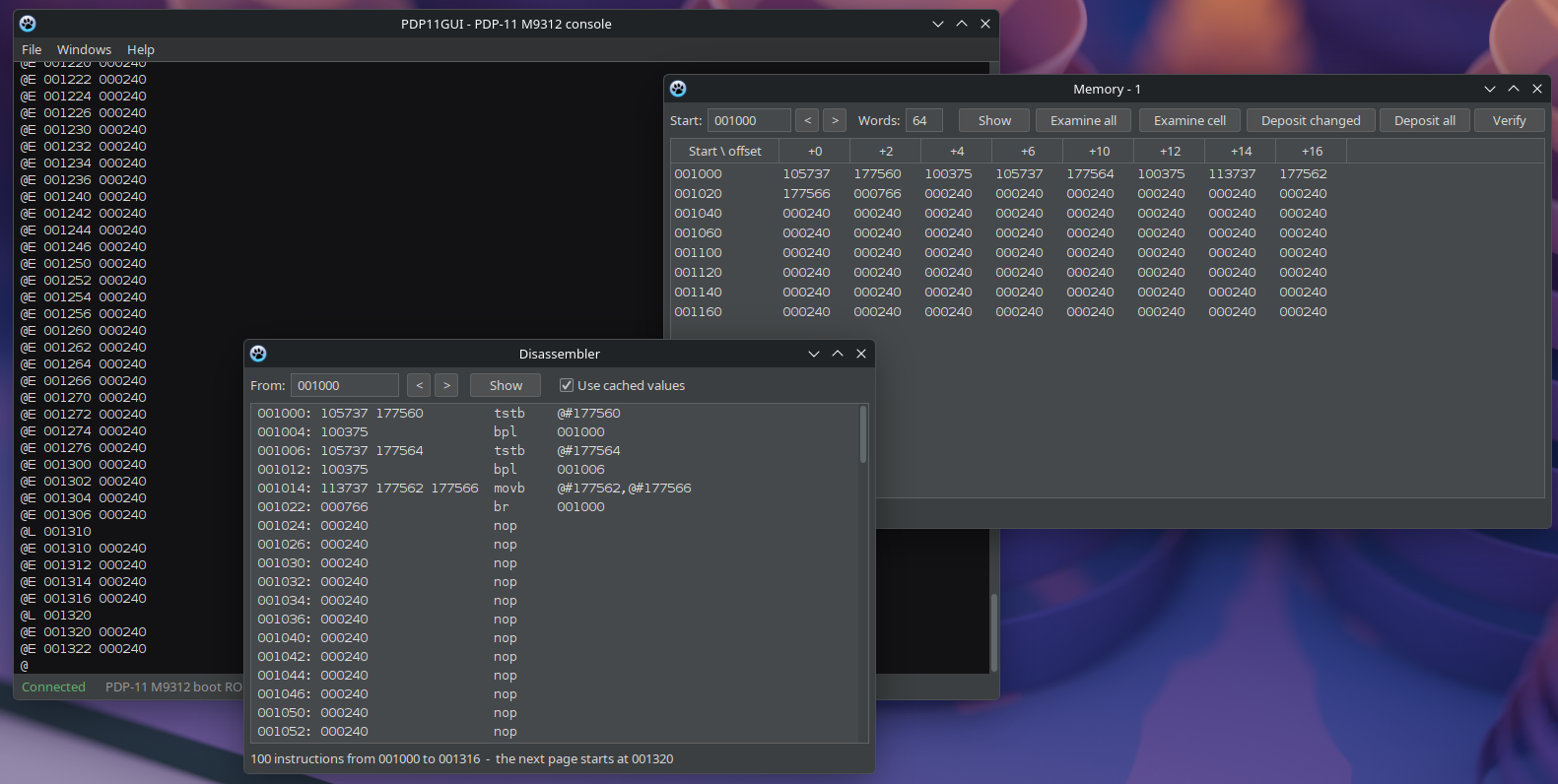
I loaded the example tic-tac-toe game and this works as hoped: