
The DD11-DK and DD11-CK backplanes
The DD11-DK backplane
The DD11-DK backplane is a generic 9 slot Unibus backplane:
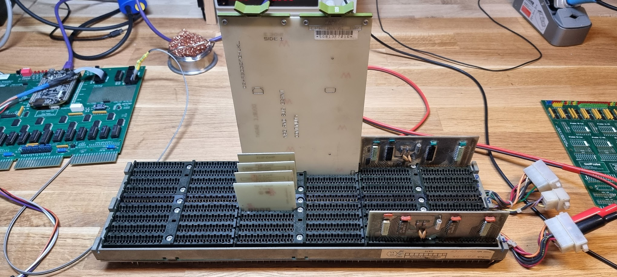
It has the following configuration:
| A | B | C | D | E | F | |
|---|---|---|---|---|---|---|
| 9 | UNIBUS | SPC | ||||
| 8 | Modified UNIBUS | SPC | ||||
| 7 | Modified UNIBUS | SPC | ||||
| 6 | Modified UNIBUS | SPC | ||||
| 5 | Modified UNIBUS | SPC | ||||
| 4 | Modified UNIBUS | SPC | ||||
| 3 | Modified UNIBUS | SPC | ||||
| 2 | Modified UNIBUS | SPC | ||||
| 1 | UNIBUS | SPC |
The power connectors are configured as follows:
P2 Connector: Amp 15 pin MATE-N-LOC
| Pin | AWG | Color | Function | Slot Pins |
|---|---|---|---|---|
| 1 | 14 | red | +5V | AA2, BA2, CA2, DA2, EA2, FA2 |
| 2 | 18 | grey | +15V | CU1 |
| 3 | 14 | orange | +20V core | AU1, AV1, AV2 |
| 4 | 14 | red | +5V | AA2, BA2 |
| 5 | ||||
| 6 | ||||
| 7 | ||||
| 8 | 14 | black | GND | |
| 9 | 14 | black | GND | |
| 10 | ||||
| 11 | ||||
| 12 | 14 | red | +5VB | BD1 |
| 13 | ||||
| 14 | 18 | brown | -5V core | BV2 |
| 15 |
P3 Connector: Amp 6 pin MATE-N-LOC
| Pin | AWG | Color | Function | Slot Pins |
|---|---|---|---|---|
| 1 | 14 | black | GND | |
| 2 | 18 | brown | LTC | CD1 |
| 3 | 18 | violet | DCLO | BF2, CN1 |
| 4 | 18 | yellow | ACLO | BF1 |
| 5 | ||||
| 6 |
P4 Connector: Amp 15 pin MATE-N-LOC
| Pin | AWG | Color | Function | Slot Pins |
|---|---|---|---|---|
| 1 | 14 | red | +5V | AA2, BA2, CA2, DA2, EA2, FA2 |
| 2 | ||||
| 3 | 14 | orange | +20V core | AU1, AV1, AV2 |
| 4 | 14 | red | +5V | AA2, BA2, CA2, DA2, EA2, FA2 |
| 5 | ||||
| 6 | 18 | white | +15VB | AR1 |
| 7 | ||||
| 8 | 14 | black | GND | |
| 9 | 14 | black | GND | |
| 10 | ||||
| 11 | ||||
| 12 | ||||
| 13 | 18 | blue | -15V | CB2, CC2, CD2, CE2, CF2 |
| 14 | ||||
| 15 | 18 | green | -15VB | AS1 |
Connecting +5V to this backplane can be done as follows, on P2:
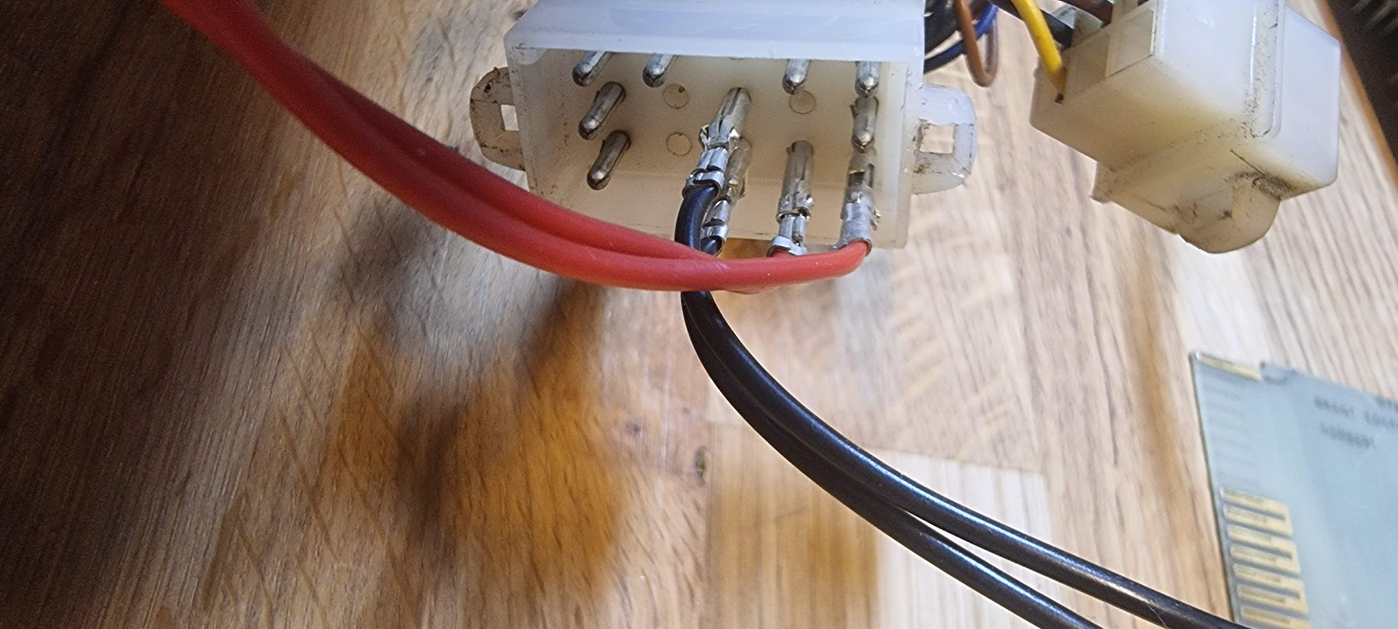
Make sure this is P2; it should be written on the plug itself, if not take good note of the pin layout.
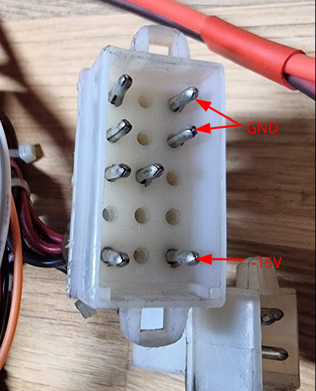
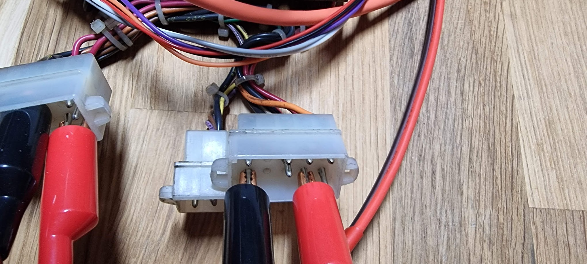
Connecting -15V (for the Delua controller) must be done on P4, as follows:
The DD11-CK backplane
This backplane is a generic 4 slot backplane:
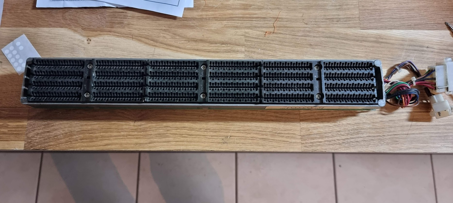
The slots are numbered 1 to 4, starting the closest to the edge of the table. Connectors A are to the right; F is to the left. It has the following configuration:
| A | B | C | D | E | F | |
|---|---|---|---|---|---|---|
| 4 | UNIBUS | SPC | ||||
| 3 | Modified UNIBUS | SPC | ||||
| 2 | Modified UNIBUS | SPC | ||||
| 1 | UNIBUS | SPC |
This backplane has two connectors for power:
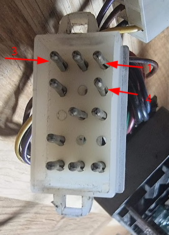
and
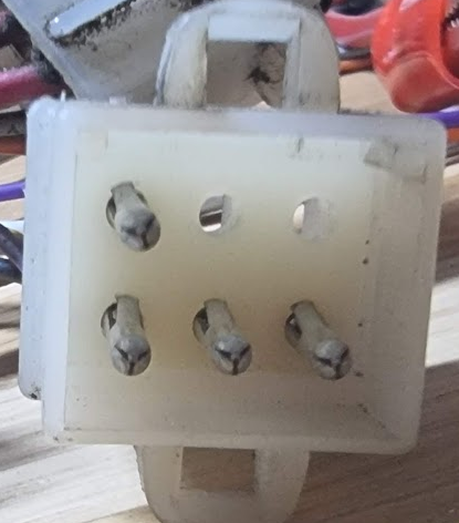
Power connector pinout:
| Pin | AWG | Color | Function | Slot Pins |
|---|---|---|---|---|
| 1 | 14 | red | +5V | AA2, BA2, CA2, DA2, EA2, FA2 |
| 2 | 18 | grey | +15V | CU1 |
| 3 | orange | |||
| 4 | 14 | red | +5V | AA2, BA2 |
| 5 | white | |||
| 6 | ||||
| 7 | 14 | black | GND | |
| 8 | 14 | black | GND | |
| 9 | ||||
| 10 | ||||
| 11 | ||||
| 12 | red | |||
| 13 | 18 | blue | -15V | CB2, CC2, CD2, CE2, CF2 |
| 14 | brown | |||
| 15 | green |