
The H740 Power Supply
According to Gunkies the power supply for this model is unspecified. It looks like this:
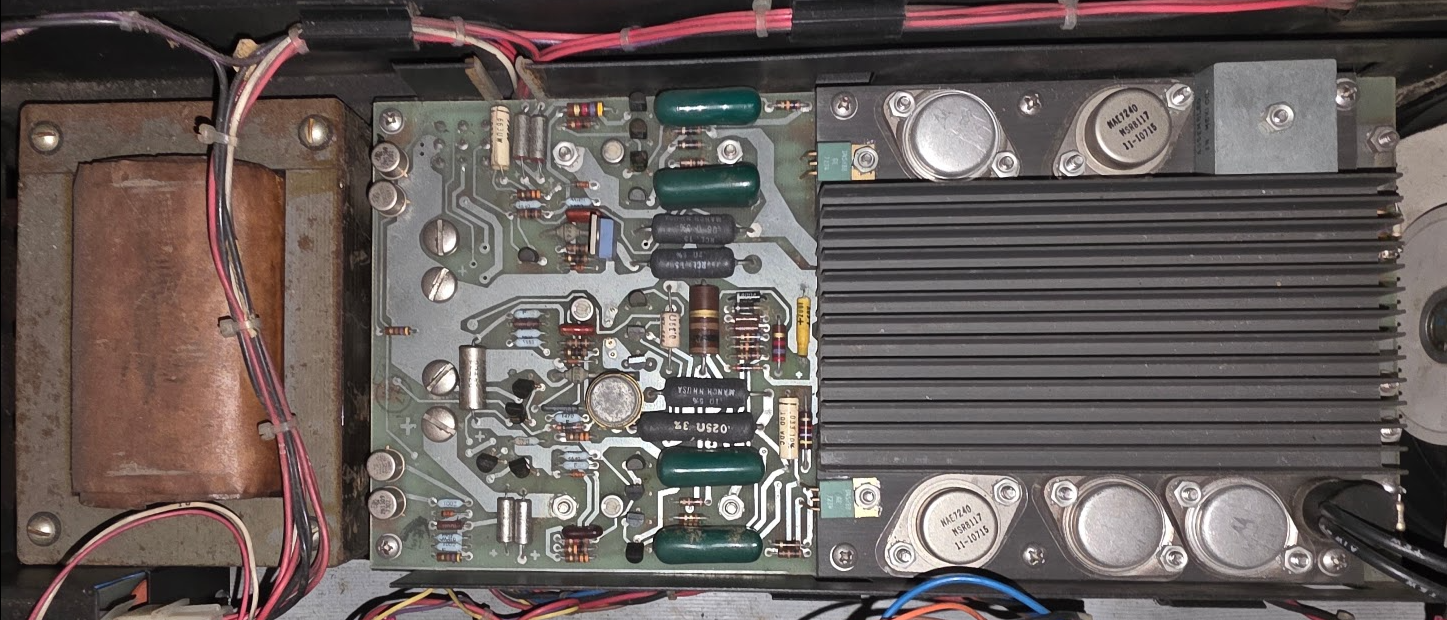
But in my 11/05 technical drawings that board with the large cooling fin is called the "Regulator for the H740" with number 5409728. This is indeed the number present on the PCB, so I think it will be that. This power supply is (apparently used in the PDP 8 too)[https://forum.vcfed.org/index.php?threads/h740-power-supply-whats-your-q1.1238205/].
The PSU's specs:
- +5V at 15A max
- +15V at 1A max, for RS-232 and bus termination, apparently
- -15V at 7A max for core memory.
Preparing the PSU for use
Capacitors...
The board has some very large capacitors. First round of business is to reform those:
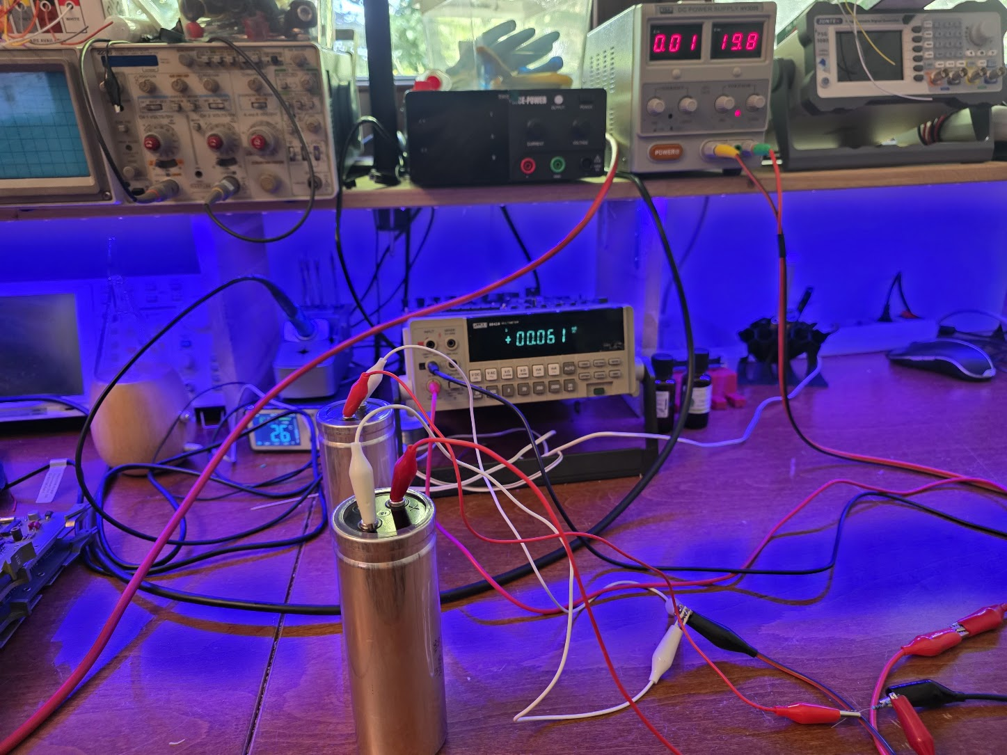
I reformed them by putting them on a voltage through a 100R resistor, slowly increasing the voltage every few hours. All of them seem to work absolutely fine after 50 years!
Getting power to the Transformer
Next step was to check the transformer, by just powering it on... That didn't work: no output from it, at all... Tracing the cabling (and cleaning it as I went, it is amazing how dirty these machines get) I found the first flaw: one of the power wires went to the console's key switch, and looking closely I could see that one of the connectors there got loose. I had to remove the console front panel to get to it, but just pressing it back restored that switch to work.
I still did not have any power, though. After more wire following I found a small 2-prong female connector which clearly meant to be connected to something because it interrupted the power; connecting both prongs got power out of the transformer which proved to be OK.
After some head scratching the cluestick hit when I looked at how the power supply fit back:
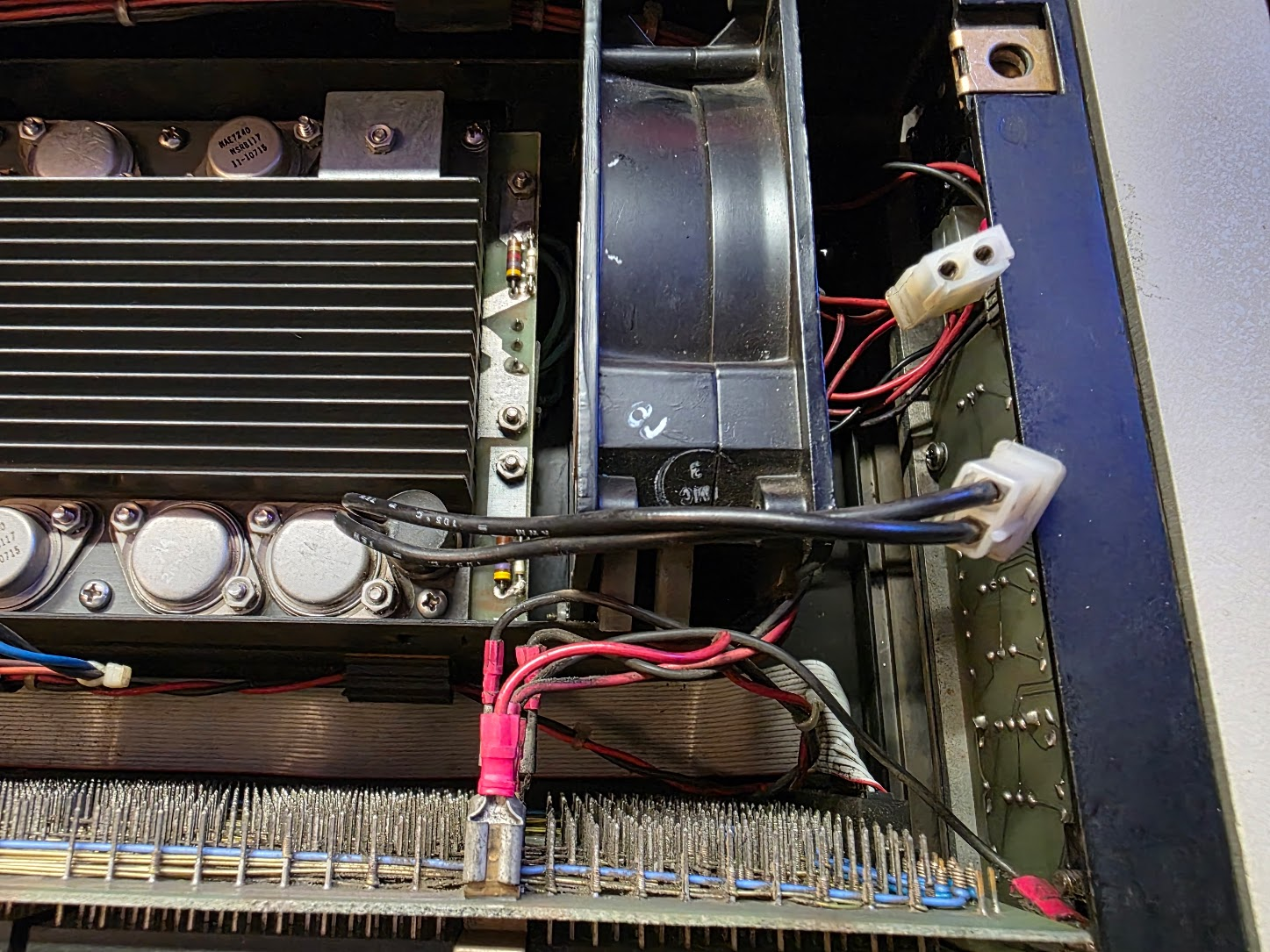
The PSU has a thermal protection, and removing the PSU of course also removed that from the plug..
Power supply standalone run
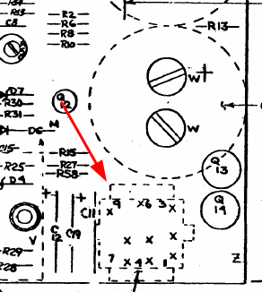
Next step is to actually run the power supply without anything attached, to see where things go. For that we need the layout of the power connector, a 9-tip MATE-LOC kind of thing. In the schematic drawings this thing is annotated as follows:
First check was the fuses, those were both OK. Next is to measure voltages.
With the connector at the right (and looking on top of the PCB, connector pointing down) the pinout is as follows:
9 6 3
8 5 2
7 4 1
The pinout, then, according to the schematic:
| Pin | Name | Function |
|---|---|---|
| 1 | BUS AC LO L | Becomes L when AC power drops |
| 2 | GND | |
| 3 | +5V | |
| 4 | LTC L | The 50Hz signal for the clock function inside the PDP 11 |
| 5 | +15V | |
| 6 | BUS DC LO L | Becomes L when DC voltage becomes too low |
| 7 | PWR OK ENABLE | |
| 8 | PWR OK | |
| 9 | -15V |
I soldered some wires to the power plug and added a 3ohm resistor to the 5V channel. That produced the following measurements:
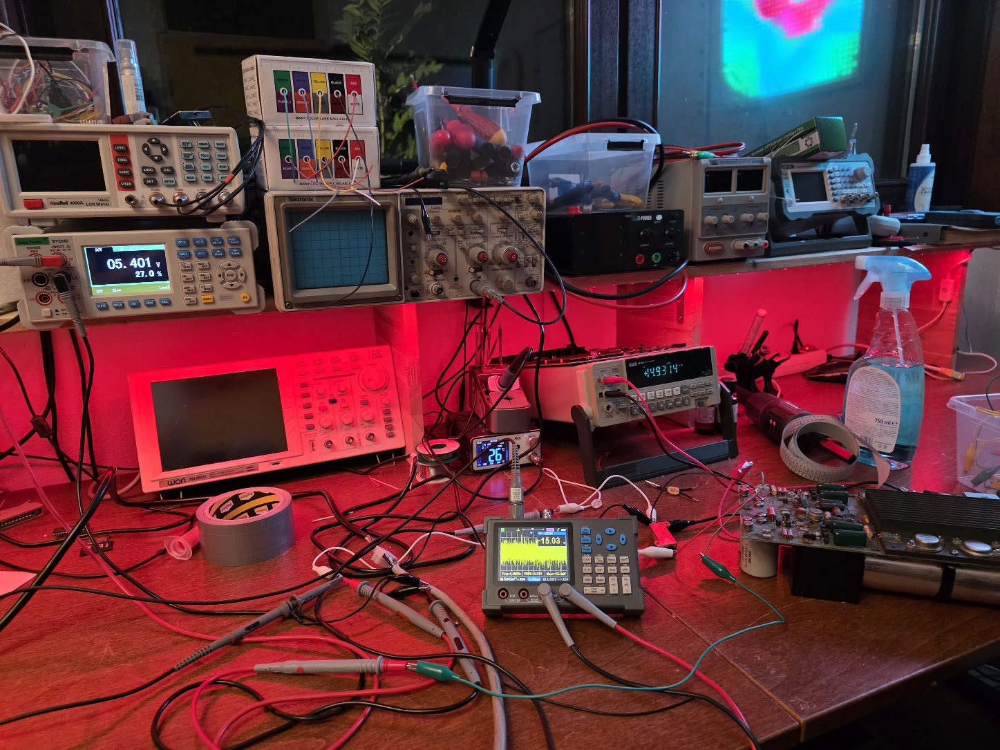
Yes, lots of different meters, but each of them showed a reasonable voltage, although the 5V one is a bit high. The voltages can be fixed with the three potentiometers on the power supply.
The PSU has crossbars over all power outputs, so we should not get into an overvoltage situation...
Other signals
I measured pin 1 (BUS AC LO L), 4V; pin 6 (BUS DC LO L), 4V and pin 8 (PWR OK), 4V.
Heads-up: in the next part it was found that the BUS DC LO L and AC LO L signals were not a fixed voltage: they were a 15% low, rest high block pulse at 100Hz. This measured as the about 4V and caused issues, of course.