Tektronix 2236

An Ebay find which was quite dirty.

The device does switch on but there is no trace on the screen. The multimeter board shows “fail-d”, and after a while shows “no trig” even though the instrument is set up so that it should (1KHz sine wave of 4Vpp input on A used as signal). No trigger setting causes a display at all.

Power supply voltages all seem fine.

Pressing the “beam find” button DOES show something in the screen, and it even vaguely resembles a real waveform, so:

  • The high voltage seems OK
  • The fault might be around the Z drive

Following the trigger circuitry:
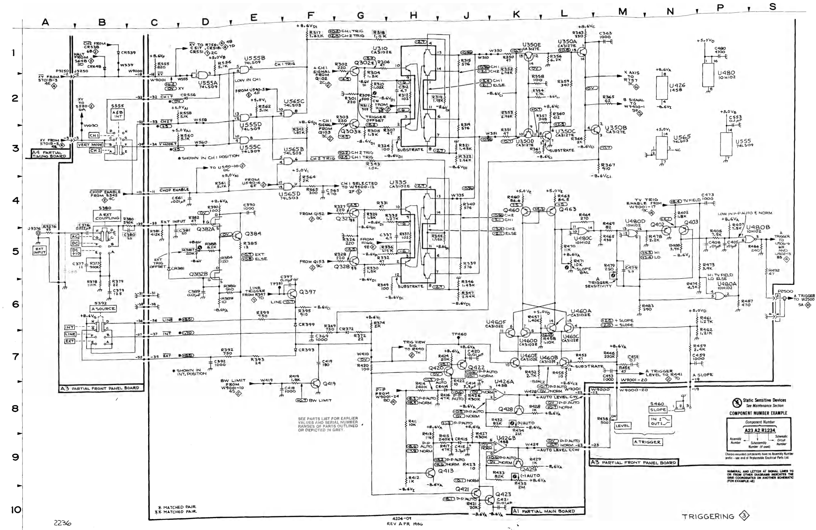
Diagram 3, the triggering section, from the A trigger comparators through U460 to the A TRIGGER output at P2500.

Checking U480D pin 15 does indicate that triggers are detected although something seems off: the trigger signal (a square wave) on XXXX rides on a high DC voltage which seems odd:
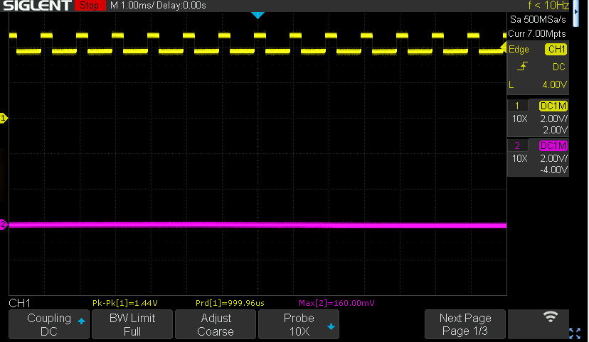
Triggers are being detected: a 1.44V square wave at 1ms per division. The trace sits high up the screen, well off the zero marker at the left.

Checking the Z drive circuitry with trigger pulses present:
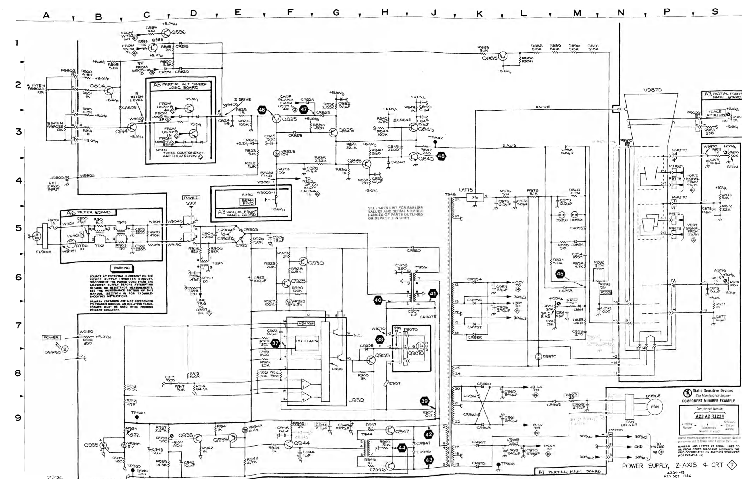
Diagram 7, power supply, Z axis and CRT. Q825 is at test point 46 near the top left, where the Z drive starts.

Looking at Q825 (MP 46) shows a constant voltage of around 1.4v This voltage nicely jumps when BEAM FIND is pressed to around 4.3v. Cleaning the intensity pots fixed that, and with that there IS a trace, on both channels. Yippy

The multimeter board

Next round is to look at the multimeter board’s fail-d error. This indicates a problem with reference voltages according to the manual.

Round 2: magic smoke (blue star)

While I used the scope it suddenly started to have problems on the image: the sides of the image started to crawl to the center. After that I smelled magic smoke, so I quickly switched off the scope.

I fear some component in the PSU will have died.

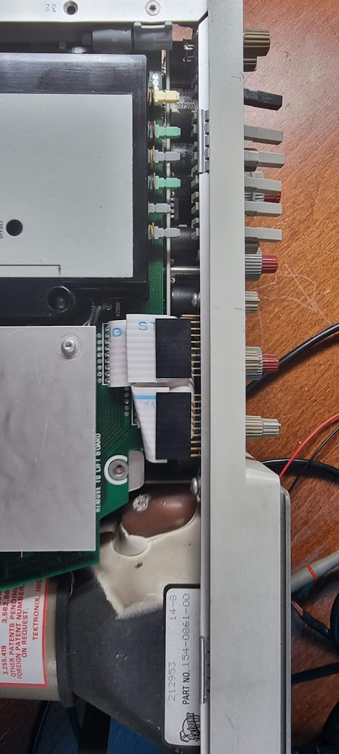
To fix this I need to remove the DMM board. First remove all buttons from it (use a screwdriver to open them, then pull them back. Then remove the two flatcables and unscrew 3 screws that hold the DMM board connected.

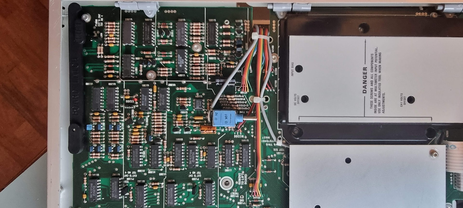
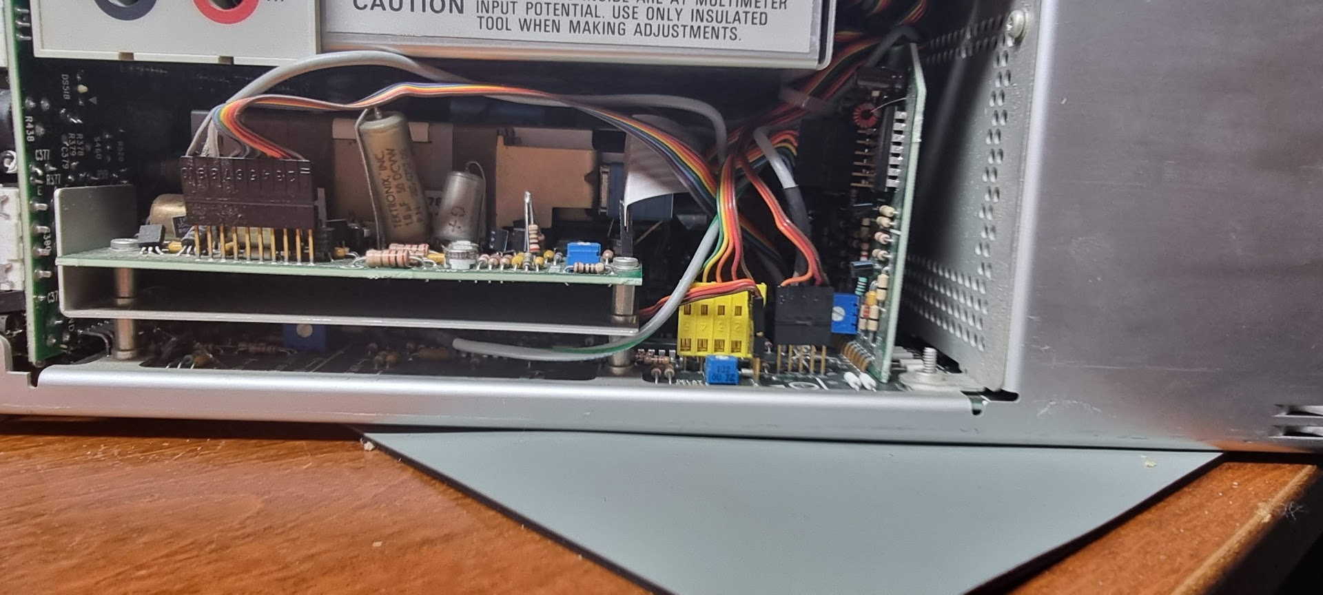
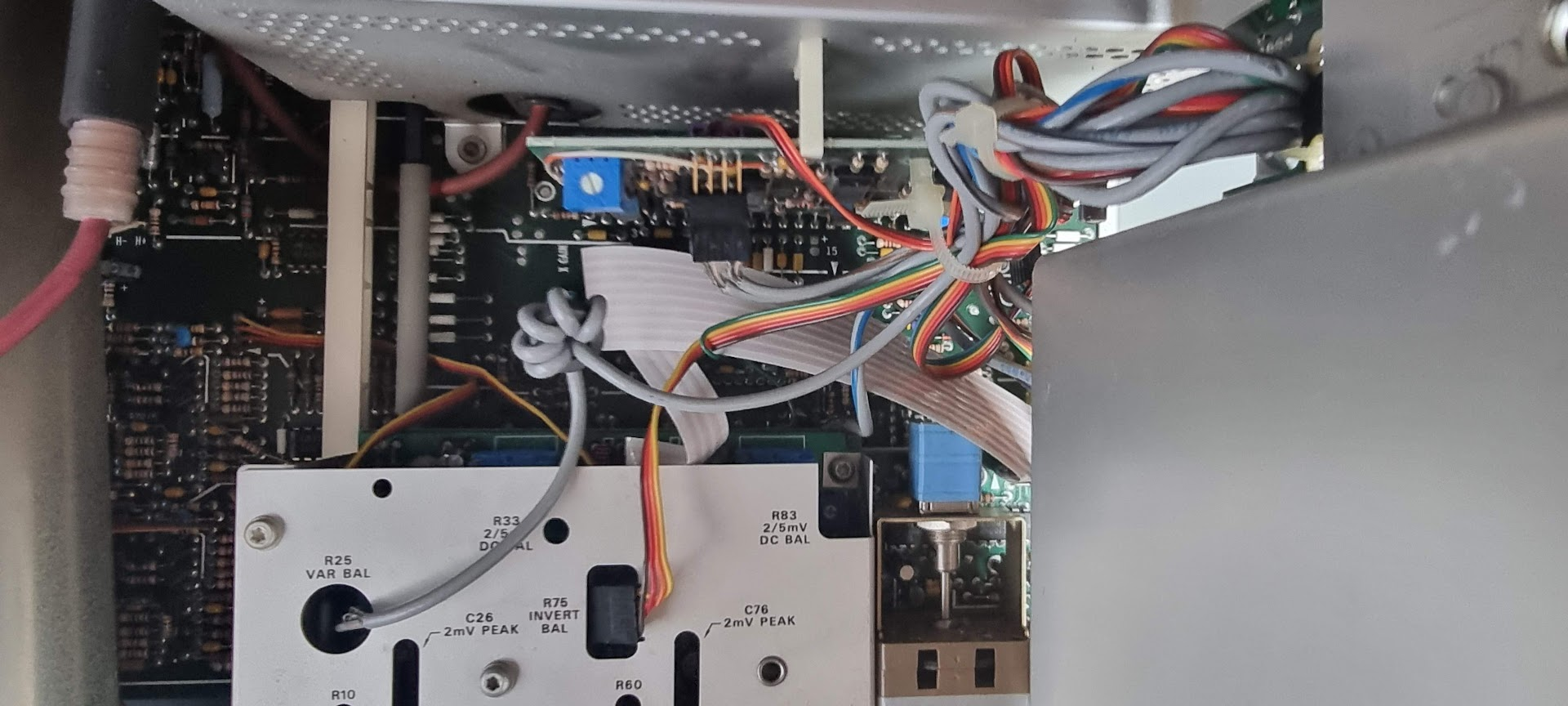
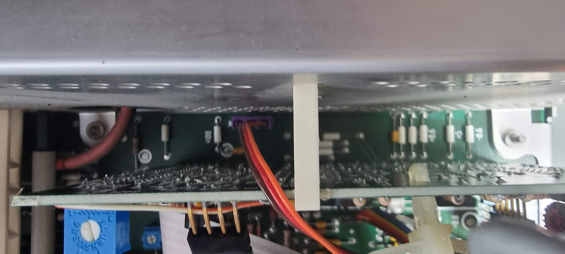
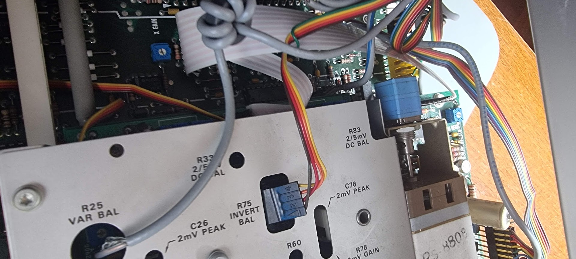
Images for the wiring around the DMM board:
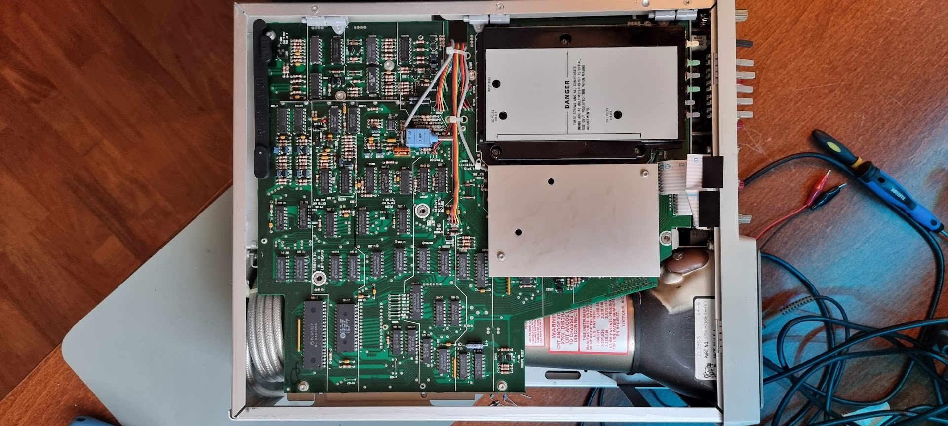
The scope opened with the DMM board still fitted, seen from above with the CRT neck at the bottom right.
The two ribbon cables that have to come off the DMM board, at the front edge behind the button row.
The main board underneath once the DMM board is out, with the hysteresis pot and the ribbon that runs up to it.
The DMM board from the side, showing the standoffs it sits on and the yellow connector block at its lower edge.
The adjustment plate below it: R25 VAR BAL, R33 and R83 DC BAL, and the C26 and C76 2mV PEAK trimmers.
Looking along the gap between the two boards to see how they stack and where the loom passes between them.
The same plate from the other side, with the grey and rainbow looms routed over it and R76 2mV GAIN at the bottom right.
Last modified: 2026/09/06