Home Vintage Equipment Digital
HP 1600A Logic Analyzer
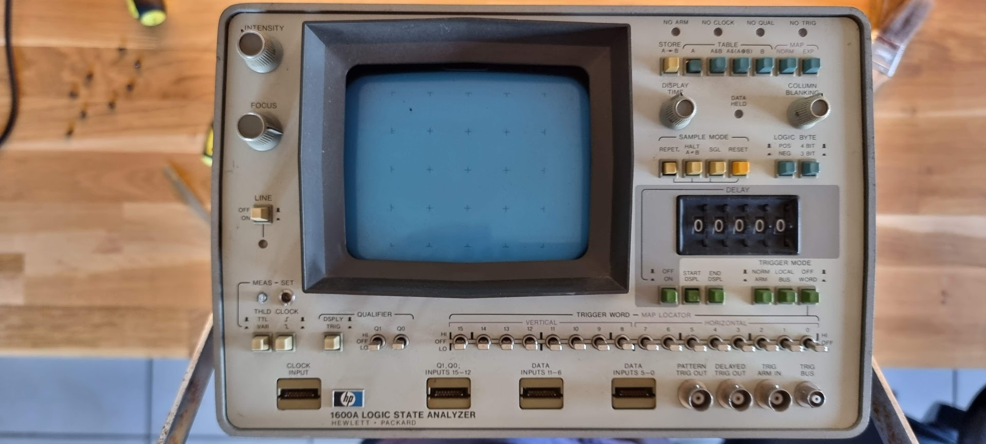
HP 1600A Logic Analyzer

The 1600A front panel: the sixteen trigger word switches along the bottom, the delay thumbwheels at the right, and the four NO ARM to NO TRIG lamps across the top.

Gotten from the inheritance of Domaine l’Espitalet. This device is one of the first logical analyzers from HP and a companion of the HP 1607A I already have. The device seemed in good physical shape, just a bit dirty. But sadly enough it did not work. A quick measure of the +5V showed that no power was present there.

The insides looked quite clean too:
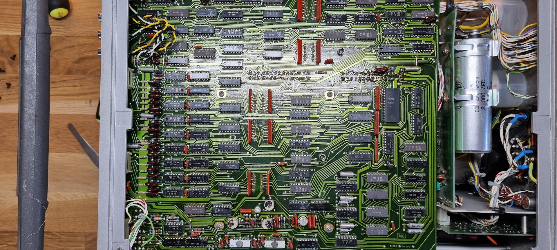
Inside, with the A1 board filling the frame and the two large supply cans visible at the right.
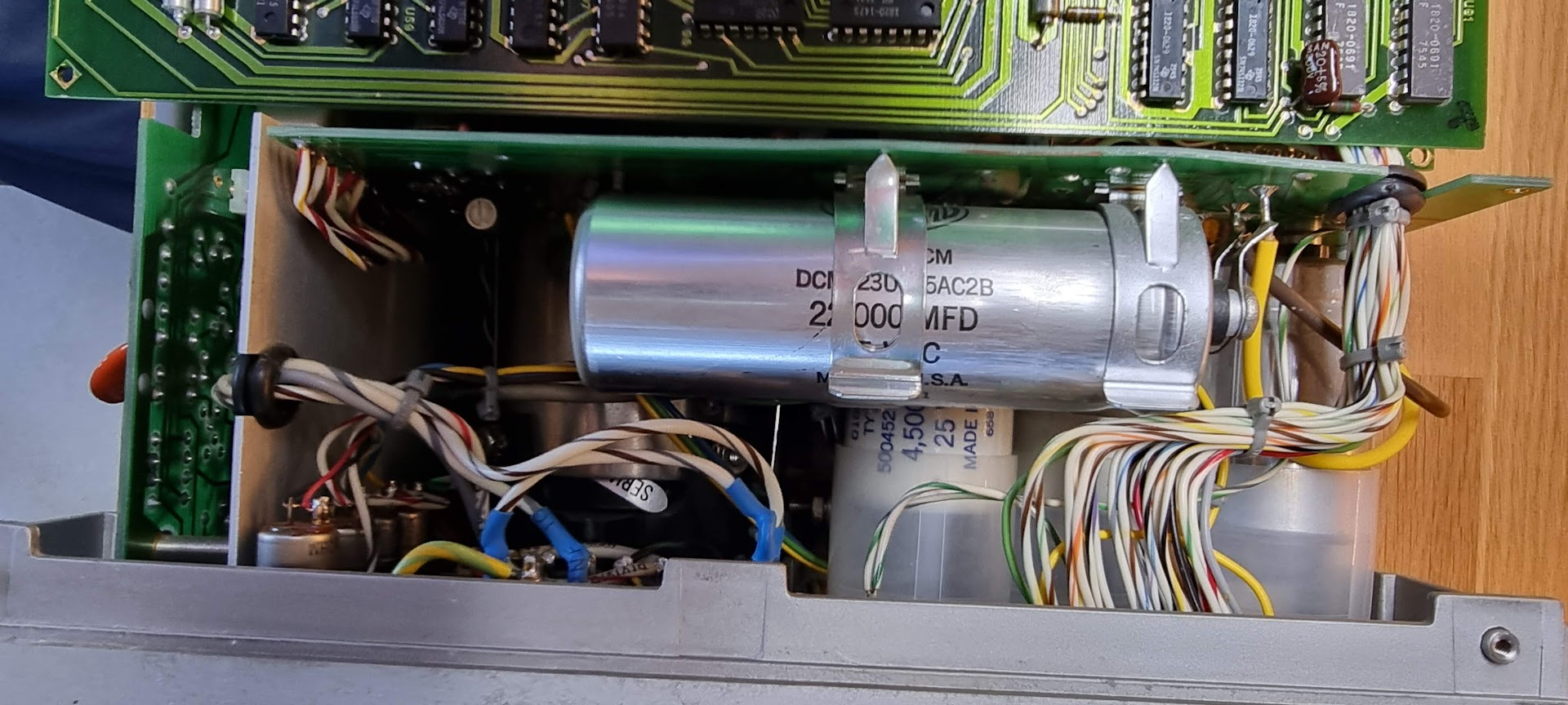
The supply behind the board: a 22000uF can on top and a 4500uF one underneath it.

Repairing the device

First step is to get access to the power supply. First remove the A1 board, taking care of the connectors at the top:
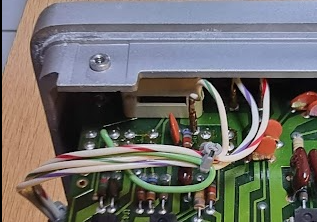
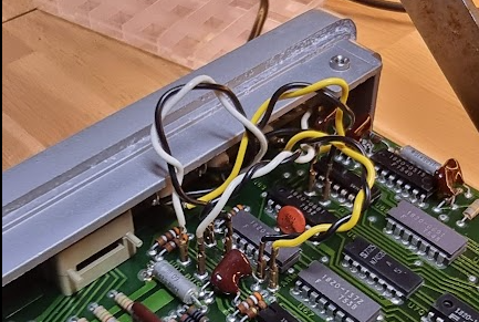
The connectors at the top edge of A1 that have to come off before the board can be lifted.
The other set on the same edge. The PCB carries markings that repeat the plug names on the front panel.

For the top right ones the PCB has markings that echo the plugs at front.

Power supply

The schematic was stitched together from the service manual:
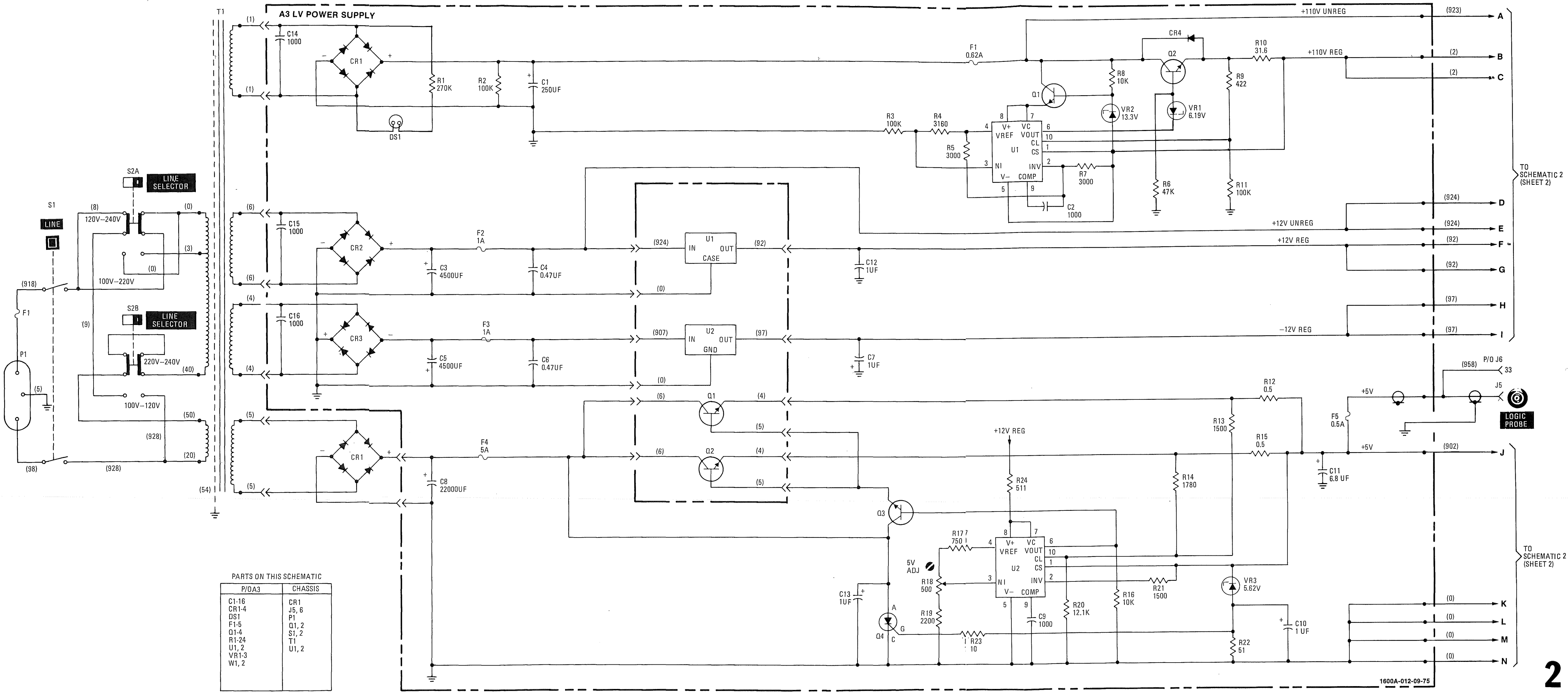
The A3 low voltage supply, stitched together from the service manual. The +5V rail is the bottom section: a 5A fuse, the 22000uF C8, series transistors Q1 and Q2, and a uA723 at U2 with R12 and R15 as the 0.5 ohm current sense pair.

Disconnecting everything showed that +12, -12, +5 were all fine, until I put load on the +5V line. Even 200mA dropped it to 200mV.

Part numbers in that power supply:

Q1, Q2 M552 4-433 Hfe=43, Hfe=29
Q3 2N3053
U1 case 1826-0147 7812
U2 case 1826-0221 7912
U1, U2 brd uA723 Voltage regulator

The current sensing resistors seemed fine at 0.5ohm.

Last modified: 2026/09/06