Backplanes - detailed slot descriptions
Notes: DD11 Unibus Backplane
Unibus Backplanes
| Type | Slots | Description |
|---|---|---|
| DD11-A | 4 | The end slots are Unibus in rows A and B, one of the middle sp;slots, row A is for the power connection. Rows C to F are SPC. |
| DD11-B | 4 | The end slots are Unibus in rows A and B, the middle slots, rows A and B are for DF11. Rows C to F are SPC. Power connection is via a harness and faston tabs. |
| DD11-CF | 4 | The end slots are Unibus in rows A and B, the middle slots, rows A and B are MUD (?). Rows C to F are SPC. Power connection is via a soldered harness for a BA11-F mounting box. |
| DD11-CK | 4 | The end slots are Unibus in rows A and B, the middle slots, rows A and B are MUD (?). Rows C to F are SPC. Power connection is via a soldered harness for a BA11-K mounting box. |
| DD11-DF | 9 | The end slots are Unibus in rows A and B, the middle slots, rows A and B are MUD (?). Rows C to F are SPC. Power connection is via a soldered harness for a BA11-F mounting box. |
| DD11-DK | 9 | The end slots are Unibus in rows A and B, the middle slots, rows A and B are MUD (?). Rows C to F are SPC. Power connection is via a soldered harness for a BA11-K mounting box. |
Detailed Slot Descriptions
Backplanes viewed from the wiring side.
DD11-A
| A | B | C | D | E | F | |
| 4 | UNIBUS | SPC | ||||
| 3 | Power | unused | SPC | |||
| 2 | unavailable | unused | SPC | |||
| 1 | UNIBUS | SPC |
DD11-B
| A | B | C | D | E | F | |
| 4 | UNIBUS | SPC | ||||
| 3 | DF11 | SPC | ||||
| 2 | DF11 | SPC | ||||
| 1 | UNIBUS | SPC |
DD11-C
| A | B | C | D | E | F | |
| 4 | UNIBUS | SPC | ||||
| 3 | Modified UNIBUS | SPC | ||||
| 2 | Modified UNIBUS | SPC | ||||
| 1 | UNIBUS | SPC |
DD11-D
| A | B | C | D | E | F | |
| 9 | UNIBUS | SPC | ||||
| 8 | Modified UNIBUS | SPC | ||||
| 7 | Modified UNIBUS | SPC | ||||
| 6 | Modified UNIBUS | SPC | ||||
| 5 | Modified UNIBUS | SPC | ||||
| 4 | Modified UNIBUS | SPC | ||||
| 3 | Modified UNIBUS | SPC | ||||
| 2 | Modified UNIBUS | SPC | ||||
| 1 | UNIBUS | SPC |
UNIBUS Pin Designations
| Row A | Row B | |||
| 1 | 2 | 1 | 2 | |
| A | INIT L | +5V | BG6 H | +5V |
| B | INTR L | GND | BG5 H | GND |
| C | D00 L | GND | BR5 L | GND |
| D | D02 L | D01 L | GND | BR4 L |
| E | D04 L | D03 L | GND | BG4 H |
| F | D06 L | D05 L | AC LO L | DC LO L |
| H | D08 L | D07 L | A01 L | A00 L |
| J | D10 L | D09 L | A03 L | A02 L |
| K | D12 L | D11 L | A05 L | A04 L |
| L | D14 L | D13 L | A07 L | A06 L |
| M | PA L | D15 L | A09 L | A08 L |
| N | GND | PB L | A11 L | A10 L |
| P | GND | BBSY L | A13 L | A12 L |
| R | GND | SACK L | A15 L | A14 L |
| S | GND | NPR L | A17 L | A16 L |
| T | GND | BR7 L | GND | C1 L |
| U | NPG H | BR6 L | SSYN L | C0 L |
| V | BG7 SO | GND | MSYN L | GND |
aa
Modified UNIBUS Pin Designations
| Row A | Row B | |||
| 1 | 2 | 1 | 2 | |
| A | INIT L | +5V | RESV | +5V |
| B | INTR L | GND | RESV | TP |
| C | D00 L | GND | BR5 L | GND |
| D | D02 L | D01 L | +5 BAT | BR4 L |
| E | D04 L | D03 L | INT SSYN | PAR DET |
| F | D06 L | D05 L | AC LO L | DC LO L |
| H | D08 L | D07 L | A01 L | A00 L |
| J | D10 L | D09 L | A03 L | A02 L |
| K | D12 L | D11 L | A05 L | A04 L |
| L | D14 L | D13 L | A07 L | A06 L |
| M | PA L | D15 L | A09 L | A08 L |
| N | PAR P1 | PB L | A11 L | A10 L |
| P | PAR P0 | BBSY L | A13 L | A12 L |
| R | +15 BAT | SACK L | A15 L | A14 L |
| S | -15 BAT | NPR L | A17 L | A16 L |
| T | GND | BR7 L | GND | C1 L |
| U | +20 CORE | BR6 L | SSYN L | C0 L |
| V | +20 CORE | +20 CORE | MSYN L | -5 CORE |
Unibus / Modified unibus difference
| Row A | Row B | |||||||
| 1UB | 1MUD | 2UB | 2MUD | 1UB | 1MUD | 2UB | 2MUD | |
| A | INIT L | +5V | BG6 H | RESV | +5V | |||
| B | INTR L | GND | BG5 H | RESV | GND | TP | ||
| C | D00 L | GND | BR5 L | GND | ||||
| D | D02 L | D01 L | GND | +5V BAT | BR4 L | |||
| E | D04 L | D03 L | GND | INT SSYN | BG4 H | PAR DET | ||
| F | D06 L | D05 L | AC LO L | DC LO L | ||||
| H | D08 L | D07 L | A01 L | A00 L | ||||
| J | D10 L | D09 L | A03 L | A02 L | ||||
| K | D12 L | D11 L | A05 L | A04 L | ||||
| L | D14 L | D13 L | A07 L | A06 L | ||||
| M | PA L | D15 L | A09 L | A08 L | ||||
| N | GND | PAR P1 | PB L | A11 L | A10 L | |||
| P | GND | PAR P0 | BBSY L | A13 L | A12 L | |||
| R | GND | +15V BAT | SACK L | A15 L | A14 L | |||
| S | GND | -15V BAT | NPR L | A17 L | A16 L | |||
| T | GND | BR7 L | GND | C1 L | ||||
| U | NPG H | +20 CORE | BR6 L | SSYN L | C0 L | |||
| V | BG7 SO | +20 CORE | GND | +20 CORE | MSYN L | GND | -5V CORE |
SPC Pin Designations
| Row C | Row D | Row E | Row F | |||||
| 1 | 2 | 1 | 2 | 1 | 2 | 1 | 2 | |
| A | NPG IN | +5V | TP | +5V | GND | +5V | ABG OUT | +5V |
| B | NPG OUT | -15V | TP | -15V | ASSYN IN H | -15V | ABG IN | -15V |
| C | PA L | GND | A SEL 6 | GND | A12 L | GND | SSYN L | GND |
| D | LTC | D15 L | A OUT L | BR7 L | A17 L | A15 L | BBSY L | F01 N1 |
| E | TP | D14 L | A SEL 4 | BR6 L | MSYN L | A16 L | F01 V2 | D02 L |
| F | TP | D13 L | A SEL 0 | BR5 L | A02 L | C1 L | D05 L | D06 L |
| H | D11 L | D12 L | A IN | BR4 L | A01 L | A00 L | D07 L | A INT ENBB |
| J | A INT B | D10 L | A SEL 4 | A BR OUT | SSYN L | C0 L | NPR L | GND A |
| K | TP | D09 L | A OUT | BG7 SO | A14 L | A13 L | D08 L | A INT B |
| L | A INT ENBB | D08 L | INIT L | BG7 OUT | A11 L | TP | D03 L | F01 L2 |
| M | TP | D07 L | A INT ENBA | BG6 SO | A IN | A OUT H | INTR L | F01 M2 |
| N | DC LO | D04 L | A INT A | BG6 OUT | A OUT L | A08 L | F01 N1 | D04 L |
| P | HALT REQ | D05 L | TP | BG5 SO | A10 L | A07 L | ABR OUT | F01 P2 |
| R | HALT GRT | D01 L | TP | BG5 OUT | A09 L | A SEL 4 | F01 L2 | F01 N1 |
| S | PB L | D00 L | TP | BG4 SO | A SEL 6 | A SEL 0 | F01 M2 | F01 P2 |
| T | GND | D03 L | GND | BG4 OUT | GND | A SEL 2 | GND | SACK L |
| U | +15/+8 | D02 L | TP | ABG IN | A06 L | A04 L | A INT A | ABR OUT |
| V | AC LO | D06 L | ASSYN IN H | ABG OUT | A05 L | A03 L | A INT ENBA | F01 F01 |
11/40 Power Distribution Panel
Connector: AMP 9 pin MATE-N-LOC™
| Pin | AWG | Color | Function | Slot Pins |
| 1 | 18 | violet | DCLO | BF2, CN1 |
| 2 | 18 | yellow | ACLO | BF1 |
| 3 | 18 | blue | -15V | CB2, CC2, CD2, CE2 |
| 4 | 14 | black | GND | |
| 5 | 14 | black | GND | |
| 6 | n/c | |||
| 7 | 18 | brown | LTC | CD1 |
| 8 | 14 | grey | +15V | CU1 |
| 9 | 14 | red | +5V | AA2, BA2, CA2, DA2, EA2, FA2 |
DD11-DK Power Connections
P2 Connector: AMP 15 pin MATE-N-LOC™ (Also on DD11-CK)
| Pin | AWG | Color | Function | Slot Pins |
| 1 | 14 | red | +5V | AA2, BA2, CA2, DA2, EA2, FA2 |
| 2 | 18 | grey | +15V | CU1 |
| 3 | 14 | orange | +20V core | AU1, AV1, AV2 |
| 4 | 14 | red | +5V | AA2, BA2 |
| 5 | ||||
| 6 | ||||
| 7 | ||||
| 8 | 14 | black | GND | |
| 9 | 14 | black | GND | |
| 10 | ||||
| 11 | ||||
| 12 | 14 | red | +5VB | BD1 |
| 13 | ||||
| 14 | 18 | brown | -5V core | BV2 |
| 15 |
P3 Connector: AMP 6 pin MATE-N-LOC™ (Also on DD11-CK)
| Pin | AWG | Color | Function | Slot Pins |
| 1 | 14 | black | GND | |
| 2 | 18 | brown | LTC | CD1 |
| 3 | 18 | violet | DCLO | BF2, CN1 |
| 4 | 18 | yellow | ACLO | BF1 |
| 5 | ||||
| 6 |
P4 Connector: AMP 15 pin MATE-N-LOC™ (Not available on DD11-CK)
| Pin | AWG | Color | Function | Slot Pins |
| 1 | 14 | red | +5V | AA2, BA2, CA2, DA2, EA2, FA2 |
| 2 | ||||
| 3 | 14 | orange | +20V core | AU1, AV1, AV2 |
| 4 | 14 | red | +5V | AA2, BA2, CA2, DA2, EA2, FA2 |
| 5 | ||||
| 6 | 18 | white | +15VB | AR1 |
| 7 | ||||
| 8 | 14 | black | GND | |
| 9 | 14 | black | GND | |
| 10 | ||||
| 11 | ||||
| 12 | ||||
| 13 | 18 | blue | -15V | CB2, CC2, CD2, CE2 |
| 14 | ||||
| 15 | 18 | green | -15VB | AS1 |


Power supply connectors
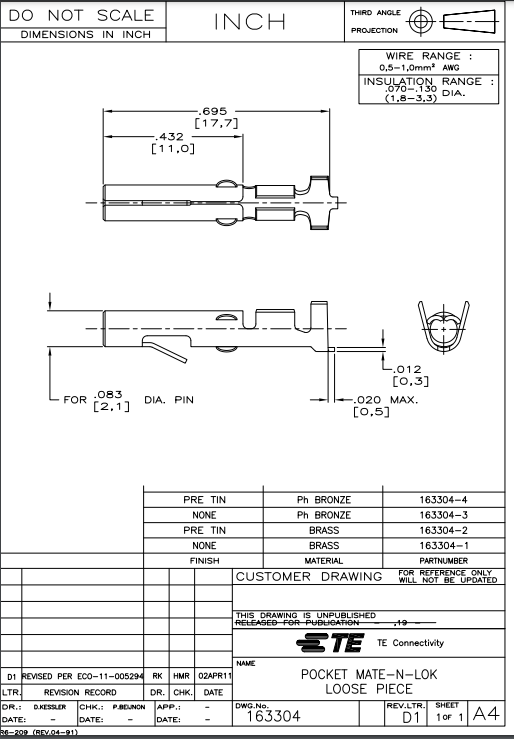
These connectors are all “MATE-N-LOK” connectors from TE Connectivity. This connector family consists of housings and pins sold separately in different form factors and pin sizes. Some parts can be obtained from conrad.nl; search for MATE-N-LOK.
I got the following to work with the connectors:
- TE Connectivity 163304-2 Krimpcontact MATE-N-LOK, female pin, max 15A, 17 AWG Max, 20AWG Min, min dwarsdoortsnede 0.5mm2, max 1.0mm2
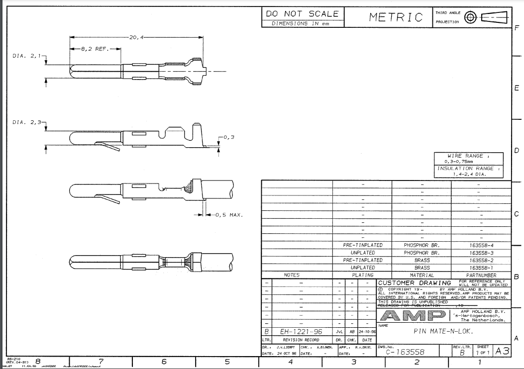
The corresponding pin seems to be this:
- TE Connectivity 163558-2 Krimpcontact MATE-N-LOK, 15A, max 18AWG, min 22AWG,
A male housing that is not fully compatible but which has at least proper spacing seems to be this: