Using the RL02 as an USB drive
Incomplete, in progress.
There is a project on the Internet where someone created a board which allows the RL02 to be used as an USB drive. The project is quite old (10 years in 2025) and not well described; there is just a Github repo without instructions. I got a board for this project from Ed, and am trying to get the code on that board - and the result to work. This document is the log of things done so far..
The project
The project can be found here.
The repo contains the KiCAD board design, the gerbers and everything else to get the board constructed. The board consists of:
- A microcontroller (a Texas Instruments Tiva TM4C1232D5PM)
- A Xilinx FPGA (a XC3S50A-4VQ100).
The FPGA does all of the heavy work; the uC is used to implement the USB mass storage part only.
Installing the required software
Building and installing the uC code
Installing the required SDKs
Download the USB Driver library and the peripheral driver libraries described in the project from the TI website. This should result in two files:
- SW-TM4C-DRL-2.2.0.295-peripheral-drivers.exe
- SW-TM4C-USBL-2.2.0.295-USB-drivers.exe
These are executables that we cannot use under Linux, but they can be unpacked using "Ark". Extract these into the directory where you installed ccs, for instance ~/opt/ccs. The directories can then be renamed to driverlib and usb to get rid of the terrible names.
After that start ccstudio, open the project, go to the RL02 controller project, use the right mouse and select Properties and change the include paths:
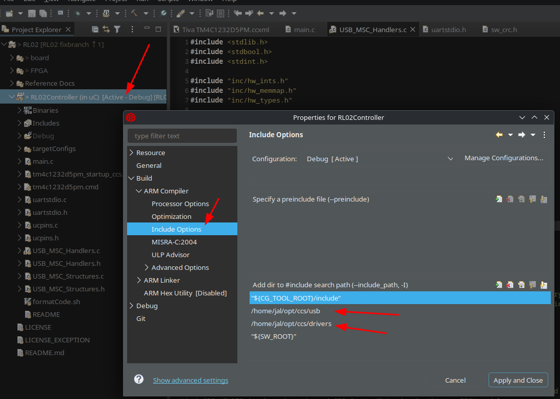
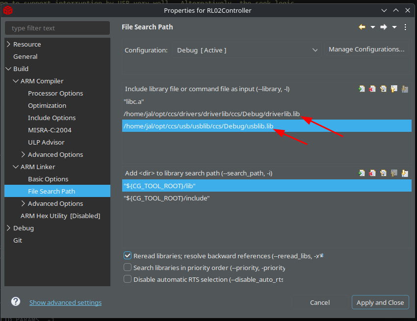
After that add the paths also to the linker settings:
Building the code
Before you build the code we need to add missing configuration to the build, because the build as it is outputs a "RL02Controller.out" file which is an ELF file, but we need a flashable .bin file.
To add this to the build do the following:
- Open the RL02Controller project properties
- Select the "Build" tab at the left
- Select the "Steps" tab in the tab panel
- Enter the following in the Post-Build steps:
${CCE_INSTALL_ROOT}/utils/tiobj2bin/tiobj2bin ${BuildArtifactFileName} ${BuildArtifactFileBaseName}.bin ${CG_TOOL_ROOT}/bin/armofd ${CG_TOOL_ROOT}/bin/armhex ${CCE_INSTALL_ROOT}/utils/tiobj2bin/mkhex4bin
(That is all one line; you will need to surround the paths with quotes if you are infected with Windows).
Once set do a "Rebuild all", which will take forever (about 8 minutes on my 48CPU Threadripper), and that should result in a RL02Controller.bin file in the Debug directory.
Flashing the uC
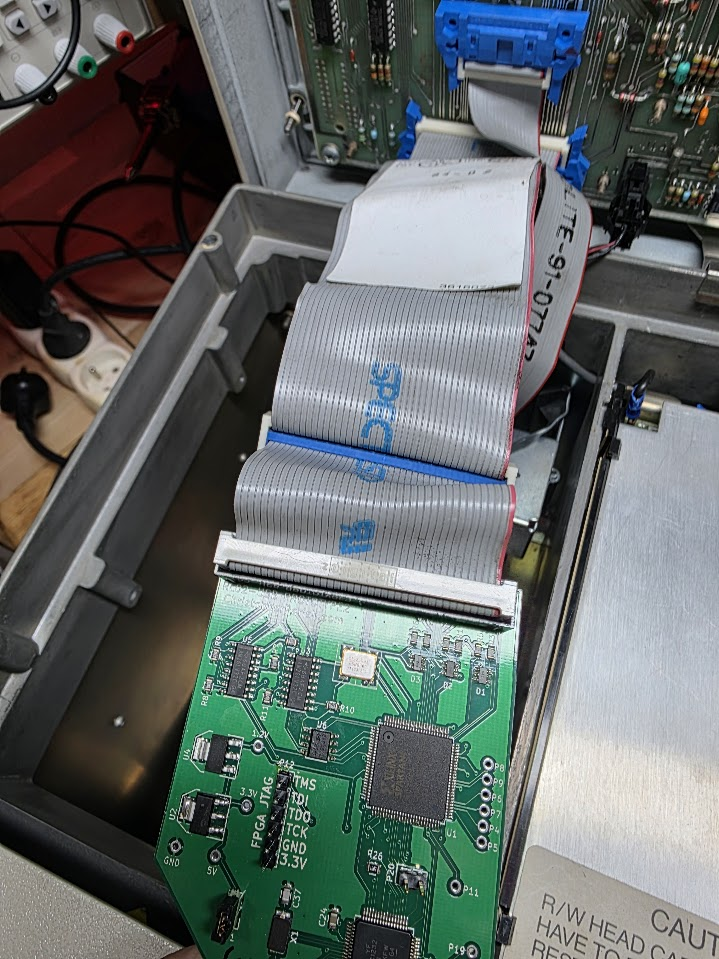
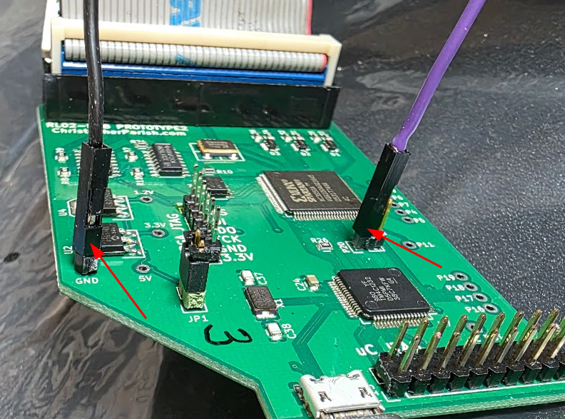
To flash the uC you need a tool that will let you. I used the Blackhawk xds100v2 tool. This needs to be connected to the board as follows:
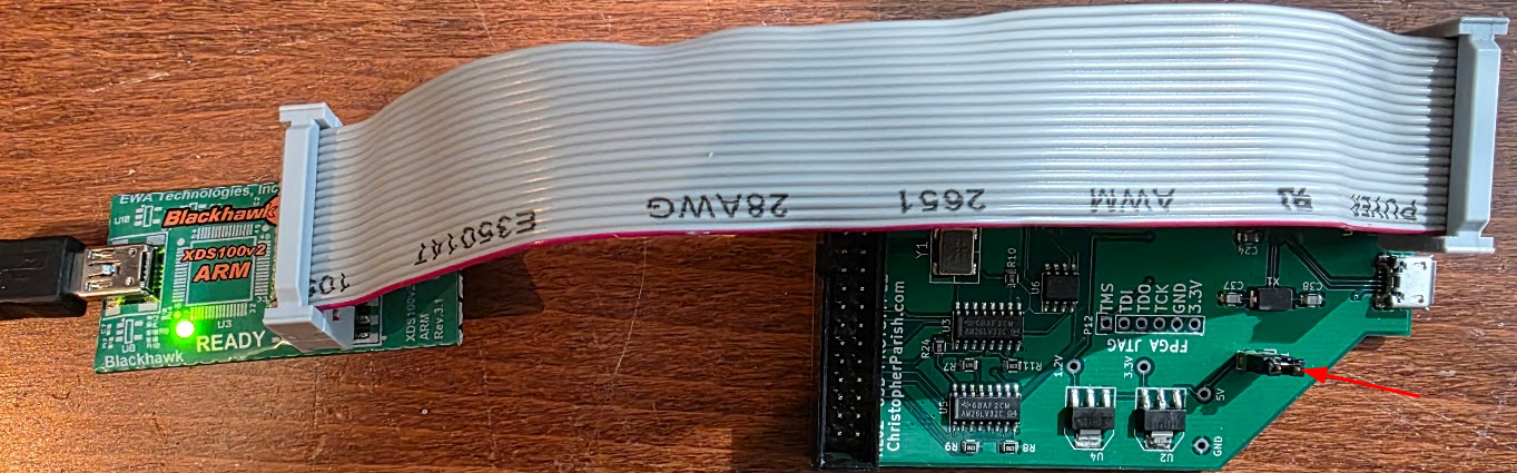
To program you need to power both the flasher and the board. To power the board make sure to place a strap on jp1, otherwise the 5V USB power will not reach the board, see the arrow in the above picture.
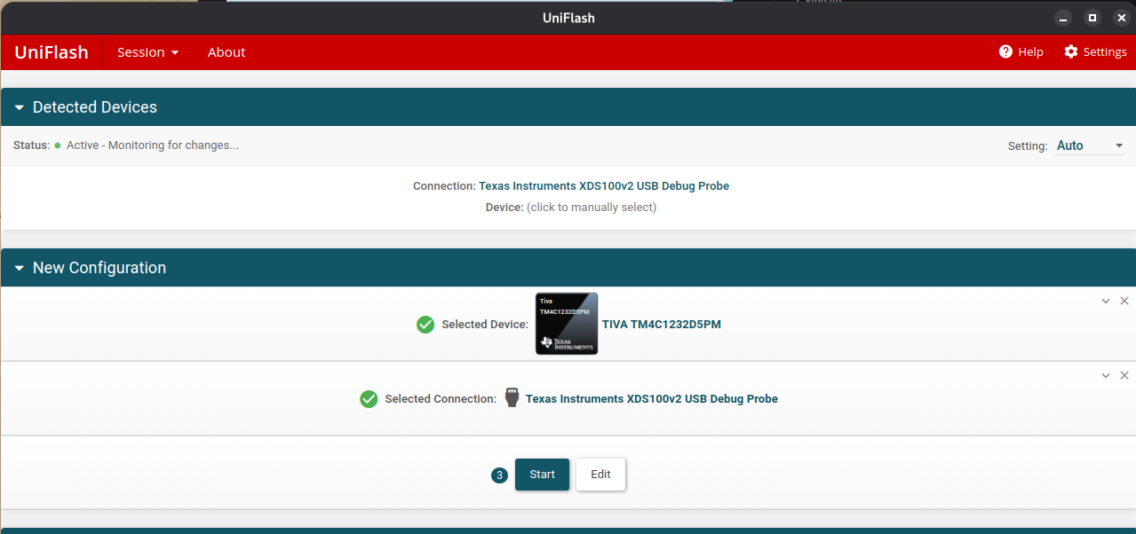
Download the flash tool (Uniflash) from here and install it.
Run the Uniflash tool, select the correct controller and device (TM4C1232C3PM):
After that press "Next", then select the compiled file:
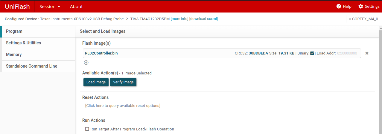
Make sure the board has its own USB connection powered too otherwise you will get a "powerloss" warning when programming. Now press the "Load Image" button, and if successful press the "Verify image" button.
Round 1: the tool said flashing was successful; the verify worked too, but after flashing I did not have USB response when connecting the board. I would have expected it to register the mass storage device..
The FPGA
Opening the FPGA code in ISE
Start ISE, then select "Open Project" and select the project file in the FPGA directory. This should open the project without too much trouble. After that do the build steps by selecting the top module, then with the right mouse button select "run":
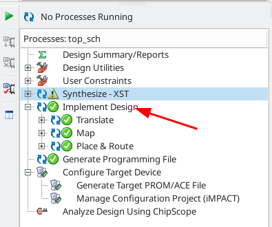
The next step is to generate the programming file using the same right mouse -> run step, followed by "Configure target device". This should open a tool called "iMPACT", which should be able to program the FPGA.
Configuring iMPACT
Use "Open Project", and load the impact file from the FPGA directory. This should show the basic configuration:
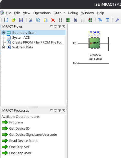
Next step is to try "program". That failed on my machine because the Xilinx USB Platform cable was not recognized. To make this work (Ubuntu Linux 25.04) do the following.
Disconnect the platform cable, then:
$ sudo apt install libusb-dev fxload
$ cd /opt/Xilinx/
$ git clone git://git.zerfleddert.de/usb-driver
$ cd usb-driver/
$ sudo make
$ ./setup_pcusb /opt/Xilinx/14.7/ISE_DS/ISE
$ sudo udevadm control --reload-rules
(Shamelessly stolen from https://askubuntu.com/questions/838260/install-xilinx-platform-usb-in-ubuntu-16-04-x64/1128841#1128841, with thanks!)
After this, reconnect the platform cable and try again; the thing should now be recognized.
This should now make the cable work.
Programming the FPGA's FLASH
Programming the FPGA only does that once; as soon as power disappears the FPGA is empty again. This is why we have the M25P10 flash aboard. It can be programmed with the bitstream for the FPGA, and at reset the FPGA will read the bitstream from that flash. The flash chip is only connected to the FPGA, so to program it we need to use a trick: we need to send something to the FPGA that will let it program the flash. This can be done fully automagically by iMPACT, The process is very well described here.
Use PROGRAM on the FLASH chip in the image, and make sure to also VERIFY.
What is in the FPGA?
The FPGA has a state machine which reads header and data bytes as they pass under the heads of the drive. Whenever a word (16 bits) is read it is put in a FIFO queue in the FPGA. This FIFO queue consists of 514 (512) entries of a 17-bit word. Bit 0..15 is the actual data, bit 16 is an indicator that the word is the first word of a header, called SPI_HEADER in the schematic and SPI_CurWordIsHeader in the top FPGA module.
Subsequent header words will not have that bit set!
The FPGA exposes the following things on GPIO port A:
- pin6: the SPI_HEADER bit as read from the FIFO.
- pin7: the data ready indicator from the SPI code.
The uC code checks the header bit when it needs to know the current sector. It waits for the word with that bit set and uses it to read the 3 words of the header. From that it can then decode the current sector number.
Initial test of the device
After flashing I connected the pcb to the RL02 by opening up the RL02, removing the flat cable from the two connectors at the back and inserting that flat cable into the PCB:
Connecting the USB cable to the PC initially does nothing. This is as expected because the code inside the uC first waits for the FPGA to signal that it has found the drive AND that it has a drive ready signal. Only then will the uC register the USB mass storage device. Switching on the drive does show that:
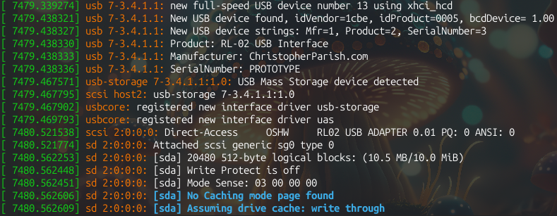
Sadly enough no I/O could be done to the device. I tried an fdisk but that hung, so something is wrong.
Extending the code with debug info
Using the TivaWare Peripheral Driver Library document I added code to configure the serial UART connected to P20 on the PCB (PA0/U0Rx, PA1/U0Tx).
I downloaded the files "uartstdio.h" and "uartstdio.c" by searching for them on Google, and copied them into the uC project. I then added the following lines to initialize the UART in main.c, just after the SPI interface initialization:
    // Set up the UART for debugging
    SysCtlPeripheralEnable(SYSCTL_PERIPH_GPIOA);
    SysCtlPeripheralEnable(SYSCTL_PERIPH_UART0);
    GPIOPinConfigure(GPIO_PA0_U0RX);
    GPIOPinConfigure(GPIO_PA1_U0TX);
    GPIOPinTypeUART(GPIO_PORTA_BASE, GPIO_PIN_0 | GPIO_PIN_1);

    UARTClockSourceSet(UART0_BASE, UART_CLOCK_PIOSC);
    UARTStdioConfig(0, 38400, 16000000);

    UARTprintf("Initialized\n");
This nicely outputs "Initialized" to the UART, which can be seen by attaching an TTY-to-USB serial adapter on P20 pin 1 (the pin more to the "inner" side of the board):
With that we can insert a lot more debugging info into the code, hopefully enough to get an idea about the issue.
Adding debugging inside the usb handlers
I added debugging info into the USB handlers. These have a few places where unexpected things happen, and the code then enters an infinite loop, which might be what we see. I added code at the entry of main methods and code for all errors that I see there. This produces the following when switching on the drive:
Initialized
MassStorage registered
read: sector 0 count 1
read: sector 0 count 1
read: sector 0 count 1
read: sector 1 count 1
read: sector 2 count 1
read: sector 3 count 1
read: sector 4 count 1
read: sector 5 count 1
read: sector 6 count 1
read: sector 7 count 1
read: sector 8 count 1
read: sector 9 count 1
read: sector 10 count 1
These sector and count numbers are in usb units of 512 bytes; the RL02 reads in sectors of 256 bytes so internally in the code these numbers double.
After that last read I tried to fdisk the drive but this hung again without any messages. Let's also add info on whether it exits read. This shows that the read for sector 10 does not finish:
read: sector 8 count 1
read: exit ok
read: sector 9 count 1
read: at track
read: exit ok
read: sector 10 count 1
and there it hangs.
First round of discovery results
I added a lot of extra debugging to see which sectors are being found and read, and this showed the following:
- The hang is caused by the code not finding a sector it needs on the drive. It loops infinitely trying to find it. In the case of that usb sector 10 it is RL02 sector 21 that cannot be found. This could of course be a problem on the disk pack I used (even though that pack did finish the RL02 XXDP tests), but changing the pack reported the error at the exact same track.
I wrote something that can quickly show the sectors that ARE found. For the 1st platter this shows (after letting the drive run for 15 minutes):
000000000011111111112222222222333333333344444444445
012345678901234567890123456789012345678901234567890
********************* **************            ***

Total sectors encountered: 2999
Number of sectors >= 40: 123
Missing are: 21, 36, 37, 38, 39
It gets worse when I add 40 to the USB sector number (in the code) so that it tries to read track 2. That does not finish at all because of CRC errors, and the cyl/head/sector from those errors show lots of issues:
seek: crc fail, 124/1/3,7679 f00/b1f5
seek: crc fail, 0/0/48,0 c005/f
seek: crc fail, 0/0/20,0 407/f005
seek: crc fail, 0/0/1,0 fc00/fc01
seek: crc fail, 0/0/3,0 3801/4400
seek: crc fail, 6/0/24,0 43/a0f6
seek: crc fail, 0/1/31,0 7cc/1412
seek: crc fail, 1/0/2,0 381f/7828
seek: crc fail, 511/1/63,65535 3f7/9401
I.e. we have bad track numbers in the header word all over the place, and impossible sector numbers too. Btw: Both of the above tests were repeated with two different platters with the same results!
Either my drive is bad, or the FPGA is doing something wrong.
FPGA Debugging
To debug, initially, it would be nice to use an FPGA-embedded debugger... For that Xilinx uses ChipScope. Install it by following this tutorial which describes the process quite well.
This document gets a bit too big, so the FPGA debugging parts go to the next document..
RL01/RL02 details
| What | RL02 | RL01 |
|---|---|---|
| Capacity | 10MB | 5MB |
| Cylinders | 512 | 256 |
| Sectors/track | 40 | 40 |
| Heads | 2 | 2 |
| Bytes/sector | 256 | 256 |
| Rotation speed | 2400rpm |