
Card connector types and pinouts
This series uses card edge connectors all over the place.
Cable end connectors
Most extension cards that have a cable will have a 2x24 pin card edge to connect the cables to. Cable connectors on these connectors must be placed with the cable exit to the RIGHT:
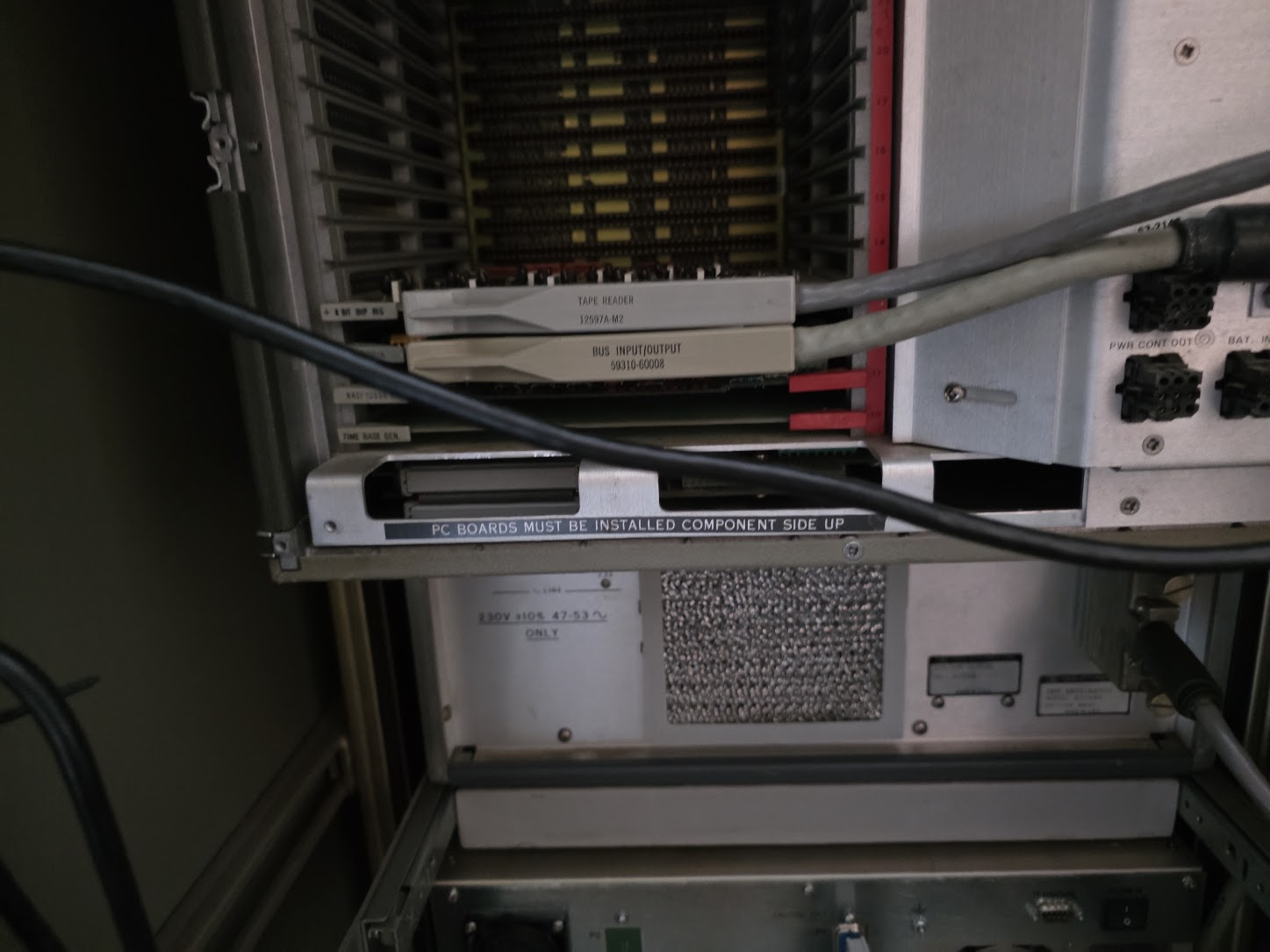
The edge connector needed for this has the following specs:
- Contacts: 48 total, arranged as two rows of 24
- Pitch: 0.156 inch (3.96 mm)
- Type: dual-readout card-edge / edge-card connector, one position keyed as a polarizing slot
- Mating part: an EDAC 305-series (or Sullins equivalent) 48-position 0.156" edge connector
and can be found here: https://eu.mouser.com/en/ProductDetail/587-305-048-500-202. The product spec is here.
The pinout for the connector, as seen from the card, is as follows:
- The component side of the board houses pin numbers 1..24
- The back side of the board houses A..BB
Looking at an example board like this:
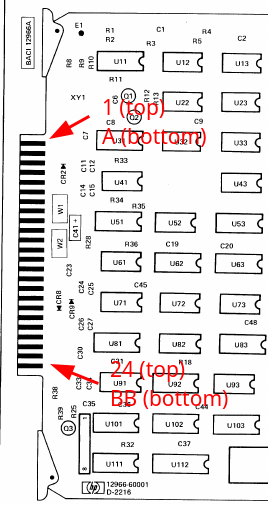
the pinout is, from top to bottom of that image:
| Component pin | Bottom pin |
|---|---|
| 1 | A |
| 2 | B |
| 3 | C |
| 4 | D |
| 5 | E |
| 6 | F |
| 7 | H |
| 8 | J |
| 9 | K |
| 10 | L |
| 11 | M |
| 12 | N |
| 13 | P |
| 14 | R |
| 15 | S |
| 16 | T |
| 17 | U |
| 18 | V |
| 19 | W |
| 20 | X |
| 21 | Y |
| 22 | Z |
| 23 | AA |
| 24 | BB |